|
1
|
INSPECT 4WD SOLENOID
• Inspect the 4WD solenoid.
• Is there any malfunction?
|
Yes
|
Replace the coupling component, then go to Step 8.
|
|
No
|
Go to the next step.
|
|
2
|
INSPECT 4WD SOLENOID POWER SUPPLY CIRCUIT FOR OPEN CIRCUIT
• Switch the ignition OFF.
• Disconnect the 4WD control module connector.
• Disconnect the 4WD solenoid connector.
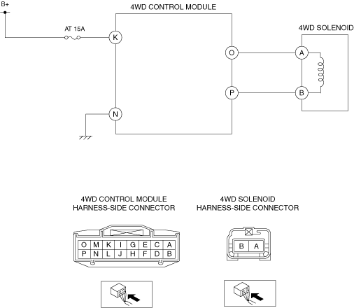
• Inspect for continuity between 4WD control module terminal O (wiring harness-side) and 4WD solenoid terminal A (wiring harness-side).
• Is there continuity?
|
Yes
|
Go to the next Step.
|
|
No
|
Refer to the wiring diagram and verify whether or not there is a common connector between 4WD control module terminal O and 4WD solenoid terminal A.
If there is a common connector:
• Determine the malfunctioning part by inspecting the common connector and the terminal for corrosion, damage, or pin disconnection, and the common wiring harness for an open circuit.
• Repair or replace the malfunctioning part.
If there is no common connector:
• Repair or replace the wiring harness which has an open circuit.
Go to Step 8.
|
|
3
|
INSPECT 4WD SOLENOID POWER SUPPLY CIRCUIT FOR SHORT TO GROUND
• Disconnect the 4WD control module connector.
• Inspect for continuity between 4WD control module terminal O (wiring harness-side) and body ground.
• Is there continuity?
|
Yes
|
Refer to the wiring diagram and verify whether or not there is a common connector between 4WD control module terminal O and 4WD solenoid terminal A.
If there is a common connector:
• Determine the malfunctioning part by inspecting the common connector and the terminal for corrosion, damage, or pin disconnection, and the common wiring harness for a short to ground.
• Repair or replace the malfunctioning part.
If there is no common connector:
• Repair or replace the wiring harness which has a short to ground.
Go to Step 8.
|
|
No
|
Go to the next step.
|
|
4
|
INSPECT 4WD SOLENOID GROUND CIRCUIT FOR OPEN CIRCUIT
• Switch the ignition OFF.
• Disconnect the 4WD control module connector.
• Disconnect the 4WD solenoid connector.
• Inspect for continuity between 4WD control module terminal P (wiring harness-side) and 4WD solenoid terminal B (wiring harness-side).
• Is there continuity?
|
Yes
|
Go to the next step.
|
|
No
|
Refer to the wiring diagram and verify whether or not there is a common connector between 4WD control module terminal P and 4WD solenoid terminal B.
If there is a common connector:
• Determine the malfunctioning part by inspecting the common connector and the terminal for corrosion, damage, or pin disconnection, and the common wiring harness for an open circuit.
• Repair or replace the malfunctioning part.
If there is no common connector:
• Repair or replace the wiring harness which has an open circuit.
Go to Step 8.
|
|
5
|
INSPECT 4WD SOLENOID GROUND CIRCUIT FOR SHORT TO GROUND
• Disconnect the 4WD control module connector.
• Inspect for continuity between 4WD control module terminal P (wiring harness-side) and body ground.
• Is there continuity?
|
Yes
|
Refer to the wiring diagram and verify whether or not there is a common connector between 4WD control module terminal P and 4WD solenoid terminal B.
If there is a common connector:
• Determine the malfunctioning part by inspecting the common connector and the terminal for corrosion, damage, or pin disconnection, and the common wiring harness for a short to ground.
• Repair or replace the malfunctioning part.
If there is no common connector:
• Repair or replace the wiring harness which has a short to ground.
Go to Step 8.
|
|
No
|
Go to the next step.
|
|
6
|
INSPECT 4WD SOLENOID POWER SUPPLY CIRCUIT FOR OPEN CIRCUIT OR SHORT TO GROUND
• Measure the voltage between 4WD control module terminal K (wiring harness-side) and body ground.
• Is the voltage B+?
|
Yes
|
Replace the 4WD control module, then go to Step 8.
|
|
No
|
Go to the next step.
|
|
7
|
INSPECT FUSE CONDITION
• Is the fuse (AT 15A) normal?
|
Yes
|
Go to the next step.
|
|
No
|
• If the fuse is blown:
-
? Refer to the wiring diagram and verify whether or not there is a common connector between fuse and 4WD control module terminal K.
If there is a common connector:
-
• Determine the malfunctioning part by inspecting the common connector and the terminal for corrosion, damage, or pin disconnection, and the common wiring harness for a short to ground.
• Repair or replace the malfunctioning part.
If there is no common connector:
-
• Repair or replace the wiring harness which has a short to ground.
• Replace the fuse.
• If the fuse is damaged:
-
? Replace the fuse.
Go to the next step.
|
|
8
|
VERIFY DTC TROUBLESHOOTING COMPLETED
• Using the M-MDS, clear the DTC from the 4WD control module.
• Drive the vehicle.
• Using the M-MDS, perform the 4WD control module DTC inspection.
• Is the same DTC present?
|
Yes
|
Replace the 4WD control module, then go to the next step.
|
|
No
|
Go to the next step.
|
|
9
|
VERIFY NO DTC IS PRESENT
• Are any DTCs present?
|
Yes
|
Go to the applicable DTC inspection.
|
|
No
|
DTC troubleshooting completed.
|