COUPLING COMPONENT REMOVAL/INSTALLATION
id031800805300
-
Caution
-
• If the characteristic value of a new coupling component is not input to the 4WD control module or the characteristic value is input incorrectly after replacing the coupling component, it could result in the following conditions:
-
? The system does not operate normally.
? A problem with durability of the coupling component occurs.
-
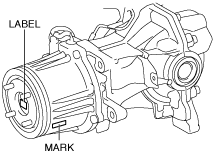
• Read out the characteristic value of the coupling component from the label or mark shown in the figure.
-
Note
-
• The 4WD control module stores the characteristic value of the coupling component before replacement.
• If the characteristic value of a new coupling component is not written, the 4WD control module does not store the value.
1. Disconnect the negative battery terminal. (See NEGATIVE BATTERY TERMINAL DISCONNECTION/CONNECTION.)
2. Drain the rear differential oil into a container. (See DIFFERENTIAL OIL REPLACEMENT.)
3. Remove the following parts:
- (1) Floor under cover No.2 (See FLOOR UNDER COVER REMOVAL/INSTALLATION.)
-
- (2) Floor under cover No.1 (See FLOOR UNDER COVER REMOVAL/INSTALLATION.)
-
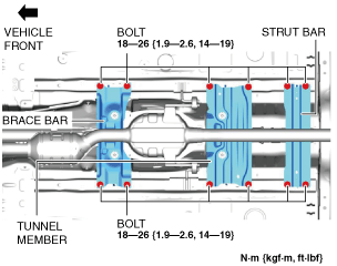
- (3) Brace bar
-
- (4) Tunnel member
-
- (5) Strut bar
-
- (6) HO2S harness bracket
-
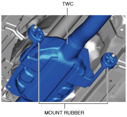
4. Remove the TWC from the mount rubber.
5. Disconnect the TWC from the main silencer. (See EXHAUST SYSTEM REMOVAL/INSTALLATION [SKYACTIV-G 2.5T].)
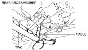
6. Suspend the TWC using a cable as shown in the figure.
7. Remove the propeller shaft. (See PROPELLER SHAFT REMOVAL/INSTALLATION.)
8. Remove in the order indicated in the table.
9. Install in the reverse order of removal.
10. Add rear differential oil. (See DIFFERENTIAL OIL REPLACEMENT.)
11. If the coupling component is replaced, write the characteristic value of a new coupling component to the 4WD control module. (See COUPLING COMPONENT CALIBRATION DATA WRITING.)
|
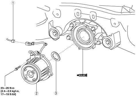
1
|
4WD solenoid connector
|
|
2
|
Coupling component
|
|
3
|
Washer
|
Coupling Component Removal Note
1. Support the coupling unit with a transmission jack.
2. Cut away the coupling unit using an oil pan seal cutter.
Coupling Component Installation Note
-
Note
-
• Clean away the remaining silicone sealant before applying new silicone sealant.
• Install the coupling component before the applied silicone sealant starts to harden.
• Add rear differential oil after the silicone sealant hardens.
1. Apply a thin layer of silicone sealant (TB1217C or equivalent) to the contact surfaces of the coupling component and the rear differential.
2. Install the coupling component to the differential.
-
Tightening torque
-
23—26 N·m {2.4—2.6 kgf·m, 17—19 ft·lbf}
 ac5ccw00000487