|
1
|
INSPECT ABS WHEEL-SPEED SENSOR (RR) DATA MONITOR
• Using the M-MDS, perform the PID inspection for ABS wheel-speed sensor (RR).
• Is the ABS wheel-speed sensor (RR) normal?
|
Yes
|
Go to Step5.
|
|
No
|
Go to the next step.
|
|
2
|
INSPECT ABS WHEEL-SPEED SENSOR (RR) SIGNAL CIRCUIT FOR SHORT TO POWER CIRCUIT
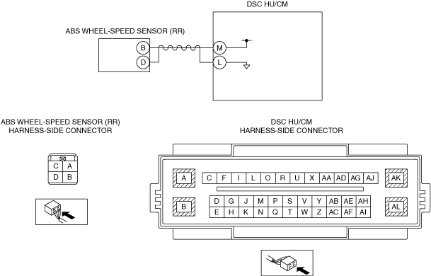
• Disconnect the ABS wheel-speed sensor (RR) connector.
• Measure the voltage between ABS wheel-speed sensor (RR) terminal D (wiring harness-side)—body ground
• Is the voltage 10 V or less?
|
Yes
|
Go to the next step.
|
|
No
|
Refer to the wiring diagram and verify whether or not there is a common connector between ABS wheel-speed sensor (RR) terminal D and DSC HU/CM terminal L.
If there is a common connector:
• Determine the malfunctioning part by inspecting the common connector and the terminal for corrosion, damage, or pin disconnection, and the common wiring harness for a short to power circuit.
• Repair or replace the malfunctioning part.
If there is no common connector:
• Repair or replace the wiring harness which has a short to power circuit.
Go to Step7.
|
|
3
|
INSPECT ABS WHEEL-SPEED SENSOR (RR) CIRCUIT FOR SHORT TO GROUND CIRCUIT
• Disconnect the ABS wheel-speed sensor (RR) connector.
• Inspect for continuity as followings:
-
? ABS wheel-speed sensor (RR) terminal B (wiring harness-side)—body ground
? ABS wheel-speed sensor (RR) terminal D (wiring harness-side)—body ground
• Is there continuity?
|
Yes
|
Refer to the wiring diagram and verify whether or not there is a common connector in the followings:
• ABS wheel-speed sensor (RR) terminal B—DSC HU/CM terminal M
• ABS wheel-speed sensor (RR) terminal D—DSC HU/CM terminal L
If there is a common connector:
• Determine the malfunctioning part by inspecting the common connector and the terminal for corrosion, damage, or pin disconnection, and the common wiring harness for a short to ground circuit.
• Repair or replace the malfunctioning part.
If there is no common connector:
• Repair or replace the wiring harness which has a short to ground circuit.
Go to Step7.
|
|
No
|
Go to the next step.
|
|
4
|
INSPECT ABS WHEEL-SPEED SENSOR (RR) CIRCUIT FOR OPEN CIRCUIT
• Disconnect the ABS wheel-speed sensor (RR) connector.
• Disconnect the DSC HU/CM connector.
• Inspect for continuity as followings:
-
? ABS wheel-speed sensor (RR) terminal B (wiring harness-side)—DSC HU/CM terminal M
? ABS wheel-speed sensor (RR) terminal D (wiring harness-side)—DSC HU/CM terminal L
• Is there continuity?
|
Yes
|
Go to the next step.
|
|
No
|
Refer to the wiring diagram and verify whether or not there is a common connector in the followings:
• ABS wheel-speed sensor (RR) terminal B—DSC HU/CM terminal M
• ABS wheel-speed sensor (RR) terminal D—DSC HU/CM terminal L
If there is a common connector:
• Determine the malfunctioning part by inspecting the common connector and the terminal for corrosion, damage, or pin disconnection, and the common wiring harness for an open circuit.
• Repair or replace the malfunctioning part.
If there is no common connector:
• Repair or replace the wiring harness which has a open circuit.
Go to Step7.
|
|
5
|
VISUALLY INSPECT ABS SENSOR ROTOR (RR)
• Visually inspect the ABS sensor rotor for foreign material adhering or improper installation.
• Is the ABS sensor rotor (RR) normal?
|
Yes
|
Go to the next step.
|
|
No
|
Replace the ABS sensor rotor (RR), then go to Step7.
|
|
6
|
INSPECT CLEARANCE BETWEEN ABS SENSOR ROTOR (RR) AND ABS WHEEL-SPEED SENSOR (RR)
• Measure the clearance between ABS sensor rotor (RR) and ABS wheel-speed sensor (RR).
• Is the clearance normal?
|
Yes
|
Go to the next step.
|
|
No
|
Replace the malfunction part, then go to the next step.
|
|
7
|
VERIFY DTC TROUBLESHOOTING COMPLETED
• Using the M-MDS, clear the DTC from the DSC HU/CM.
• Using the M-MDS, perform the DSC HU/CM DTC inspection.
• Is the same DTC present?
|
Yes
|
Repeat the inspection from Step1.
If the malfunction recurs, replace the DSC HU/CM, then go to the next step.
|
|
No
|
Go to the next step.
|
|
8
|
VERIFY NO DTC IS PRESENT
• Are any DTCs present?
|
Yes
|
Go to the applicable DTC inspection.
|
|
No
|
DTC troubleshooting completed.
|