Note
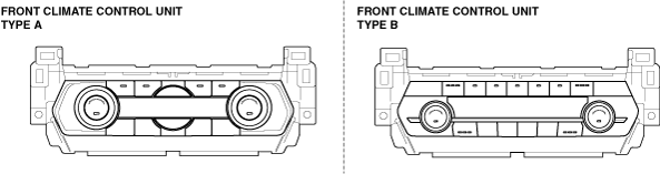
• There are two types of front climate control unit, type A and type B.
ac9wzw00005462
|
DTC B11F0:12, B11F0:13 [CLIMATE CONTROL UNIT (FULL-AUTO AIR CONDITIONER)]
id0702k2900400
ac9wzw00005462
|
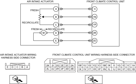
Front Climate Control Unit Type A
|
System malfunction location |
• B11F0:12: Air intake actuator (potentiometer) circuit short to power supply
• B11F0:13: Air intake actuator (potentiometer) circuit open
|
|---|---|
|
Detection condition
|
• Malfunction in wiring harness between air intake actuator and front climate control unit
|
|
Fail-safe function
|
Malfunction determined when ignition switched ON
• Air intake actuator drive signal is stopped right when the malfunction is determined. However, air intake mode is change to FRESH or RECIRCULATE when the manual operation is set to FRESH or RECIRCULATE.
Malfunction already exists when ignition switched ON
• Control based on ambient temperature. However, air intake mode is change to FRESH or RECIRCULATE when the manual operation is set to FRESH or RECIRCULATE.
|
|
Possible cause
|
• Connector or terminal malfunction
• Air intake actuator malfunction
• Open circuit in wiring harness between front climate control unit and air intake actuator
• Short to power supply in wiring harness between front climate control unit and air intake actuator
• Front climate control unit malfunction
|
 |
|
Diagnostic procedure
|
STEP |
INSPECTION |
ACTION |
|
|---|---|---|---|
|
1
|
INSPECT AIR INTAKE ACTUATOR CONNECTOR
• Switch the ignition off.
• Disconnect the negative battery terminal.
• Disconnect the air intake actuator connector.
(See AIR INTAKE ACTUATOR REMOVAL.)
• Inspect the connector and terminals (corrosion, damage, pin disconnection).
• Are the connector and terminals normal?
|
Yes
|
Go to the next step.
|
|
No
|
Repair/replace the connector or terminal.
After repair procedure, go to Step 6.
|
||
|
2
|
INSPECT AIR INTAKE ACTUATOR
• Inspect the air intake actuator.
• Is it normal?
|
Yes
|
Go to the next step.
|
|
No
|
Replace the air intake actuator.
Go to Step 6.
|
||
|
3
|
INSPECT AIR INTAKE ACTUATOR (POTENTIOMETER) CIRCUIT FOR OPEN CIRCUIT
• Disconnect the front climate control unit connector.
• Inspect for continuity between the following terminals (wiring harness-side):
• Is there continuity?
|
Yes
|
Go to the next step.
|
|
No
|
Refer to the wiring diagram and verify whether or not there is a common connector between front climate control unit terminal and air intake actuator terminal.
If there is a common connector:
• Determine the malfunctioning part by inspecting the common connector and the terminal for corrosion, damage, or pin disconnection, and the common wiring harness for an open circuit.
• Repair or replace the malfunctioning part.
If there is no common connector:
• Repair or replace the wiring harness which has an open circuit.
Go to Step 6.
|
||
|
4
|
INSPECT AIR INTAKE ACTUATOR (POTENTIOMETER) CIRCUIT FOR SHORT TO POWER SUPPLY
• Connect the negative battery terminal.
• Switch the ignition ON (engine off or on).
• Measure the voltage at the following terminals (wiring harness-side):
• Is the voltage 0 V?
|
Yes
|
Go to the next step.
|
|
No
|
Refer to the wiring diagram and verify whether or not there is a common connector between front climate control unit terminal and air intake actuator terminal.
If there is a common connector:
• Determine the malfunctioning part by inspecting the common connector and the terminal for corrosion, damage, or pin disconnection, and the common wiring harness for a short to power supply.
• Repair or replace the malfunctioning part.
If there is no common connector:
• Repair or replace the wiring harness which has a short to power supply.
Go to Step 6.
|
||
|
5
|
VERIFY FRONT CLIMATE CONTROL UNIT CONNECTOR CONDITION
• Switch the ignition off.
• Disconnect the negative battery terminal.
• Inspect the connector and terminals (corrosion, damage, pin disconnection).
• Are the connector and terminals normal?
|
Yes
|
Go to the next step.
|
|
No
|
Repair/replace the connector or terminal.
After repair procedure, go to the next step.
|
||
|
6
|
VERIFY THAT SAME DTC IS NOT OUTPUT AGAIN
• Reconnect the disconnected connectors.
• Connect the negative battery terminal.
• Clear the DTC from the climate control unit memory using the M-MDS.
• Perform the DTC inspection for the climate control unit using the M-MDS.
• Is the same DTC displayed?
|
Yes
|
Repeat the inspection from Step 1.
• If the malfunction recurs, replace the front climate control unit.
Go to the next step.
|
|
No
|
Go to the next step.
|
||
|
7
|
VERIFY THAT NO OTHER DTCs ARE PRESENT
• Verify other DTCs displayed.
• Are any other DTCs displayed?
|
Yes
|
Repair or replace the malfunctioning part according to the applicable DTC troubleshooting.
|
|
No
|
DTC troubleshooting completed.
|
||
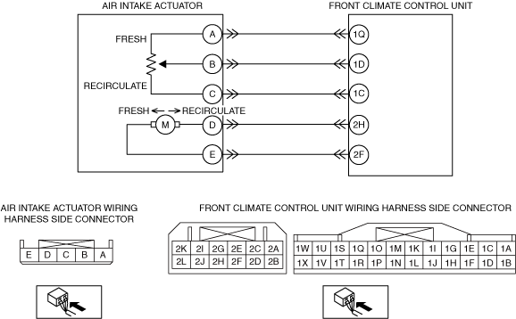
Front Climate Control Unit Type B
|
System malfunction location |
• B11F0:12: Air intake actuator (potentiometer) circuit short to power supply
• B11F0:13: Air intake actuator (potentiometer) circuit open
|
|---|---|
|
Detection condition
|
• Malfunction in wiring harness between air intake actuator and front climate control unit
|
|
Fail-safe function
|
Malfunction determined when ignition switched ON
• Air intake actuator drive signal is stopped right when the malfunction is determined. However, air intake mode is change to FRESH or RECIRCULATE when the manual operation is set to FRESH or RECIRCULATE.
Malfunction already exists when ignition switched ON
• Control based on ambient temperature. However, air intake mode is change to FRESH or RECIRCULATE when the manual operation is set to FRESH or RECIRCULATE.
|
|
Possible cause
|
• Connector or terminal malfunction
• Air intake actuator malfunction
• Open circuit in wiring harness between front climate control unit and air intake actuator
• Short to power supply in wiring harness between front climate control unit and air intake actuator
• Front climate control unit malfunction
|
 |
|
Diagnostic procedure
|
STEP |
INSPECTION |
ACTION |
|
|---|---|---|---|
|
1
|
INSPECT AIR INTAKE ACTUATOR CONNECTOR
• Switch the ignition off.
• Disconnect the negative battery terminal.
• Disconnect the air intake actuator connector.
(See AIR INTAKE ACTUATOR REMOVAL.)
• Inspect the connector and terminals (corrosion, damage, pin disconnection).
• Are the connector and terminals normal?
|
Yes
|
Go to the next step.
|
|
No
|
Repair/replace the connector or terminal.
After repair procedure, go to Step 6.
|
||
|
2
|
INSPECT AIR INTAKE ACTUATOR
• Inspect the air intake actuator.
• Is it normal?
|
Yes
|
Go to the next step.
|
|
No
|
Replace the air intake actuator.
Go to Step 6.
|
||
|
3
|
INSPECT AIR INTAKE ACTUATOR (POTENTIOMETER) CIRCUIT FOR OPEN CIRCUIT
• Disconnect the front climate control unit connector.
• Inspect for continuity between the following terminals (wiring harness-side):
• Is there continuity?
|
Yes
|
Go to the next step.
|
|
No
|
Refer to the wiring diagram and verify whether or not there is a common connector between front climate control unit terminal and air intake actuator terminal.
If there is a common connector:
• Determine the malfunctioning part by inspecting the common connector and the terminal for corrosion, damage, or pin disconnection, and the common wiring harness for an open circuit.
• Repair or replace the malfunctioning part.
If there is no common connector:
• Repair or replace the wiring harness which has an open circuit.
Go to Step 6.
|
||
|
4
|
INSPECT AIR INTAKE ACTUATOR (POTENTIOMETER) CIRCUIT FOR SHORT TO POWER SUPPLY
• Connect the negative battery terminal.
• Switch the ignition ON (engine off or on).
• Measure the voltage at the following terminals (wiring harness-side):
• Is the voltage 0 V?
|
Yes
|
Go to the next step.
|
|
No
|
Refer to the wiring diagram and verify whether or not there is a common connector between front climate control unit terminal and air intake actuator terminal.
If there is a common connector:
• Determine the malfunctioning part by inspecting the common connector and the terminal for corrosion, damage, or pin disconnection, and the common wiring harness for a short to power supply.
• Repair or replace the malfunctioning part.
If there is no common connector:
• Repair or replace the wiring harness which has a short to power supply.
Go to Step 6.
|
||
|
5
|
VERIFY FRONT CLIMATE CONTROL UNIT CONNECTOR CONDITION
• Switch the ignition off.
• Disconnect the negative battery terminal.
• Inspect the connector and terminals (corrosion, damage, pin disconnection).
• Are the connector and terminals normal?
|
Yes
|
Go to the next step.
|
|
No
|
Repair/replace the connector or terminal.
After repair procedure, go to the next step.
|
||
|
6
|
VERIFY THAT SAME DTC IS NOT OUTPUT AGAIN
• Reconnect the disconnected connectors.
• Connect the negative battery terminal.
• Clear the DTC from the climate control unit memory using the M-MDS.
• Perform the DTC inspection for the climate control unit using the M-MDS.
• Is the same DTC displayed?
|
Yes
|
Repeat the inspection from Step 1.
• If the malfunction recurs, replace the front climate control unit.
Go to the next step.
|
|
No
|
Go to the next step.
|
||
|
7
|
VERIFY THAT NO OTHER DTCs ARE PRESENT
• Verify other DTCs displayed.
• Are any other DTCs displayed?
|
Yes
|
Repair or replace the malfunctioning part according to the applicable DTC troubleshooting.
|
|
No
|
DTC troubleshooting completed.
|
||