Note
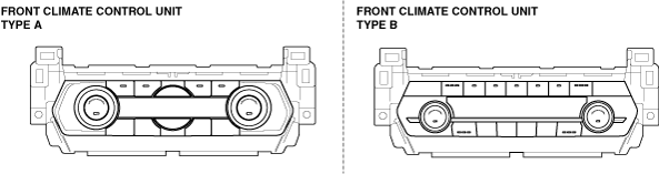
• There are two types of front climate control unit, type A and type B.
ac9wzw00005471
|
WINDSHIELD FOGGED [CLIMATE CONTROL SYSTEM]
id0703k2700700
ac9wzw00005471
|
Front Climate Control Unit Type A
|
DESCRIPTION
|
• A/C compressor does not operate while airflow mode is in DEFROSTER or DEF/HEAT modes
• Air intake mode does not change to FRESH while airflow mode is in DEFROSTER or DEF/HEAT modes
|
|
POSSIBLE CAUSE
|
• A/C compressor malfunction
• Blower unit malfunction
• ROOM 25 A fuse malfunction
• INTERIOR 10 A fuse malfunction
• Open or short circuit in wiring harness between battery positive terminal and front climate control unit
• Open or short circuit in wiring harness between front climate control unit and each actuator / sensor
• Open or short circuit in wiring harness between front climate control unit and air intake actuator position sensor
• Front climate control unit connector malfunction or poor connection
• Air intake actuator connector malfunction or poor connection
• Air intake actuator malfunction
• Air intake door malfunction
• Front climate control unit malfunction
|
Diagnostic procedure
|
Step |
Inspection |
Action |
|
|---|---|---|---|
|
1
|
COOL AIR BLOW OUT INSPECTION
• When both the A/C switch and airflow volume control switch in the front climate control unit are on, does cool air blow out from the vent?
|
Yes
|
Go to the next step.
|
|
No
|
Go to Step 1 of the following troubleshooting.
|
||
|
2
|
INSPECT FUSE
• Switch the ignition off.
• Disconnect the negative battery terminal.
• Remove the ROOM 25 A fuse and INTERIOR 10 A fuse.
• Is the fuse normal?
|
Yes
|
Go to the next step.
|
|
No
|
If the fuse is blown:
• Refer to the wiring diagram and verify whether or not there is a common connector between ROOM 25 A fuse and front climate control unit / rear climate control unit terminal.
If there is a common connector:
If there is no common connector:
• Replace the fuse.
If the fuse is damaged:
• Replace the fuse.
Then go to Step 23.
|
||
|
3*
|
INSPECT TO SEE WHETHER MALFUNCTION (OPEN CIRCUIT) IS IN B+ SIGNAL WIRING HARNESS (BETWEEN FUSE BLOCK AND FRONT CLIMATE CONTROL UNIT) OR ELSEWHERE
• Disconnect the front climate control unit connector.
• Connect the negative battery terminal.
• Switch the ignition ON (engine off or on).
• Measure voltage at the following terminal (wiring harness-side).
• Is the voltage B+?
|
Yes
|
Go to the next step.
|
|
No
|
Refer to the wiring diagram and verify whether or not there is a common connector between front climate control unit terminal and fuse block terminal.
If there is a common connector:
• Determine the malfunctioning part by inspecting the common connector and the terminal for corrosion, damage, or pin disconnection, and the common wiring harness for an open circuit.
• Repair or replace the malfunctioning part.
If there is no common connector:
• Repair or replace the wiring harness which has an open circuit.
Go to Step 23.
|
||
|
4*
|
INSPECT TO SEE WHETHER MALFUNCTION IS IN BLOWER UNIT OR AIR INTAKE ACTUATOR
• Switch the ignition off.
• Disconnect the negative battery terminal.
• Connect the front climate control unit connector.
• Connect the negative battery terminal.
• Switch the ignition ON (engine off or on).
• Measure and record voltage at the following terminal (wiring harness-side) when air intake mode at RECIRCULATE and FRESH.
• Is voltage normal?
|
Yes
|
Go to Step 22.
|
|
No
|
Go to the next step.
|
||
|
5*
|
INSPECT TO SEE WHETHER MALFUNCTION IS IN POSITION SENSOR OR ELSEWHERE
• Measure voltage at the following terminal (wiring harness-side) when airflow mode at VENT and DEFROSTER.
• Is voltage normal?
|
Yes
|
Go to Step 8.
|
|
No
|
Go to the next step.
|
||
|
6*
|
INSPECT TO SEE WHETHER MALFUNCTION (SHORT TO POWER SUPPLY OR GROUND) IS IN POSITION SENSOR POWER SUPPLY OR ELSEWHERE
• Measure voltage at the following terminal (wiring harness-side).
• Is voltage approx. 5 V?
|
Yes
|
Go to the next step.
|
|
No
|
Refer to the wiring diagram and verify whether or not there is a common connector between front climate control unit terminal and each actuator / sensor terminal.
If there is a common connector:
• Determine the malfunctioning part by inspecting the common connector and the terminal for corrosion, damage, or pin disconnection, and the common wiring harness.
• Repair or replace the malfunctioning part.
If there is no common connector:
• Repair or replace the wiring harness.
Go to Step 23.
|
||
|
7*
|
INSPECT TO SEE WHETHER MALFUNCTION (SHORT TO POWER SUPPLY) IS IN POSITION SENSOR GROUND OR ELSEWHERE
• Measure voltage at the following terminal (wiring harness-side).
• Is voltage below 1.0 V?
|
Yes
|
Refer to wiring diagram and inspect for open circuit following.
• Between front climate control unit 1R and junction point to front actuators /sensors (position sensor power supply).
• Between front climate control unit 1I and junction point to front actuators /sensors (position sensor ground).
Repair or replace the malfunctioning part or wiring harness.
Go to Step 23.
|
|
No
|
Refer to the wiring diagram and verify whether or not there is a common connector between front climate control unit terminal and each actuator / sensor terminal.
If there is a common connector:
• Determine the malfunctioning part by inspecting the common connector and the terminal for corrosion, damage, or pin disconnection, and the common wiring harness.
• Repair or replace the malfunctioning part.
If there is no common connector:
• Repair or replace the wiring harness.
Go to Step 23.
|
||
|
8*
|
INSPECT TO SEE WHETHER MALFUNCTION (SHORT TO POWER SUPPLY) IS IN WIRING HARNESS (AIR INTAKE POSITION SIGNAL) OR ELSEWHERE
• Is voltage B+, at Step 4?
|
Yes
|
Refer to the wiring diagram and verify whether or not there is a common connector between front climate control unit terminal and air intake actuator terminal.
If there is a common connector:
• Determine the malfunctioning part by inspecting the common connector and the terminal for corrosion, damage, or pin disconnection, and the common wiring harness for a short to power supply.
• Repair or replace the malfunctioning part.
If there is no common connector:
• Repair or replace the wiring harness which has a short to power supply.
Go to Step 23.
|
|
No
|
Go to the next step.
|
||
|
9
|
INSPECT FRONT CLIMATE CONTROL UNIT CONNECTOR CONNECTION CONDITION
• Switch the ignition off.
• Disconnect the negative battery terminal.
• Inspect the front climate control unit connector engagement and connection condition.
• Is the connector normal?
|
Yes
|
Go to the next step.
|
|
No
|
Reconnect the front climate control unit connector properly.
Go to Step 23.
|
||
|
10
|
INSPECT FRONT CLIMATE CONTROL UNIT CONNECTOR TERMINAL CONDITION
• Disconnect the front climate control unit connector.
• Inspect the connector and terminals (corrosion, damage, pin disconnection).
• Are the connector and terminals normal?
|
Yes
|
Go to the next step.
|
|
No
|
Repair/replace the connector or terminal.
Go to Step 23.
|
||
|
11
|
INSPECT AIR INTAKE ACTUATOR CONNECTOR CONNECTION CONDITION
• Inspect the air intake actuator connector engagement and connection condition.
(See AIR INTAKE ACTUATOR REMOVAL.)
• Is the connector normal?
|
Yes
|
Go to the next step.
|
|
No
|
Reconnect the air intake actuator connector properly.
Go to Step 23.
|
||
|
12
|
INSPECT AIR INTAKE ACTUATOR CONNECTOR TERMINAL CONDITION
• Disconnect the air intake actuator connector.
(See AIR INTAKE ACTUATOR REMOVAL.)
• Inspect the connector and terminals (corrosion, damage, pin disconnection).
• Are the connector and terminals normal?
|
Yes
|
Go to the next step.
|
|
No
|
Repair/replace the connector or terminal.
Go to Step 23.
|
||
|
13*
|
INSPECT TO SEE WHETHER MALFUNCTION (LACK OF CONTINUITY) IS IN WIRING HARNESS (AIR INTAKE POSITION SIGNAL) OR ELSEWHERE
• Inspect for continuity between the following terminals (wiring harness-side):
• Is there continuity?
|
Yes
|
Go to the next step.
|
|
No
|
Refer to the wiring diagram and verify whether or not there is a common connector between front climate control unit terminal and air intake actuator terminal.
If there is a common connector:
• Determine the malfunctioning part by inspecting the common connector and the terminal for corrosion, damage, or pin disconnection, and the common wiring harness.
• Repair or replace the malfunctioning part.
If there is no common connector:
• Repair or replace the wiring harness.
Go to Step 23.
|
||
|
14*
|
INSPECT TO SEE WHETHER MALFUNCTION (SHORT TO GROUND) IS IN WIRING HARNESS (AIR INTAKE POSITION SIGNAL) OR ELSEWHERE
• Inspect for continuity between the following terminal (wiring harness-side) and body ground:
• Is there continuity?
|
Yes
|
Refer to the wiring diagram and verify whether or not there is a common connector between front climate control unit terminal and air intake actuator terminal.
If there is a common connector:
• Determine the malfunctioning part by inspecting the common connector and the terminal for corrosion, damage, or pin disconnection, and the common wiring harness.
• Repair or replace the malfunctioning part.
If there is no common connector:
• Repair or replace the wiring harness.
Go to Step 23.
|
|
No
|
Go to the next step.
|
||
|
15*
|
INSPECT TO SEE WHETHER MALFUNCTION (OPEN CIRCUIT) IS IN POSITION SENSOR POWER SUPPLY OR ELSEWHERE
• Inspect for continuity between the following terminal (wiring harness-side) and junction point to other actuators / sensors (position sensor power supply).
• Is there continuity?
|
Yes
|
Go to the next step.
|
|
No
|
Refer to the wiring diagram and verify whether or not there is a common connector between air intake actuator terminal and junction point to other actuators / sensor terminal.
If there is a common connector:
• Determine the malfunctioning part by inspecting the common connector and the terminal for corrosion, damage, or pin disconnection, and the common wiring harness for an open circuit.
• Repair or replace the malfunctioning part.
If there is no common connector:
• Repair or replace the wiring harness which has an open circuit.
Go to Step 23.
|
||
|
16*
|
INSPECT TO SEE WHETHER MALFUNCTION (OPEN CIRCUIT) IS IN POSITION SENSOR GROUND OR ELSEWHERE
• Inspect for continuity between the following terminal (wiring harness-side) and junction point to other actuators / sensors (position sensor ground).
• Is there continuity?
|
Yes
|
Go to the next step.
|
|
No
|
Refer to the wiring diagram and verify whether or not there is a common connector between air intake actuator terminal and junction point to other actuators / sensor terminal.
If there is a common connector:
• Determine the malfunctioning part by inspecting the common connector and the terminal for corrosion, damage, or pin disconnection, and the common wiring harness for an open circuit.
• Repair or replace the malfunctioning part.
If there is no common connector:
• Repair or replace the wiring harness which has an open circuit.
Go to Step 23.
|
||
|
17*
|
INSPECT TO SEE WHETHER MALFUNCTION IS IN AIR INTAKE ACTUATOR OR WIRING HARNESS (BETWEEN FRONT CLIMATE CONTROL UNIT AND AIR INTAKE ACTUATOR)
• Connect the front climate control unit connector.
• Connect the negative battery terminal.
• Switch the ignition ON (engine off or on).
• Measure voltage at the following terminals (wiring harness-side).
• Are voltages normal?
|
Yes
|
Go to Step 21.
|
|
No
|
Go to the next step.
|
||
|
18*
|
INSPECT TO SEE WHETHER MALFUNCTION IS IN WIRING HARNESS (LACK OF CONTINUITY BETWEEN FRONT CLIMATE CONTROL UNIT AND AIR INTAKE ACTUATOR) OR ELSEWHERE
• Switch the ignition off.
• Disconnect the negative battery terminal.
• Disconnect the front climate control unit connector.
• Inspect for continuity between the following terminals (wiring harness-side):
• Is there continuity?
|
Yes
|
Go to the next step.
|
|
No
|
Refer to the wiring diagram and verify whether or not there is a common connector between front climate control unit terminal and air intake actuator terminal.
If there is a common connector:
• Determine the malfunctioning part by inspecting the common connector and the terminal for corrosion, damage, or pin disconnection, and the common wiring harness.
• Repair or replace the malfunctioning part.
If there is no common connector:
• Repair or replace the wiring harness.
Go to Step 23.
|
||
|
19*
|
INSPECT TO SEE WHETHER MALFUNCTION IS IN WIRING HARNESS (SHORT TO B+ BETWEEN FRONT CLIMATE CONTROL UNIT AND AIR INTAKE ACTUATOR) OR ELSEWHERE
• Connect the negative battery terminal.
• Switch the ignition ON (engine off or on).
• Measure voltage at the following terminals (wiring harness-side).
• Are voltages approx. 0 V?
|
Yes
|
Go to the next step.
|
|
No
|
Refer to the wiring diagram and verify whether or not there is a common connector between front climate control unit terminal and air intake actuator terminal.
If there is a common connector:
• Determine the malfunctioning part by inspecting the common connector and the terminal for corrosion, damage, or pin disconnection, and the common wiring harness for a short to power supply.
• Repair or replace the malfunctioning part.
If there is no common connector:
• Repair or replace the wiring harness which has a short to power supply.
Go to Step 23.
|
||
|
20*
|
INSPECT TO SEE WHETHER MALFUNCTION IS IN WIRING HARNESS (SHORT TO GROUND BETWEEN FRONT CLIMATE CONTROL UNIT AND AIR INTAKE ACTUATOR) OR ELSEWHERE
• Switch the ignition off.
• Inspect for continuity between the following terminals (wiring harness-side) and body ground:
• Is there continuity?
|
Yes
|
Refer to the wiring diagram and verify whether or not there is a common connector between front climate control unit terminal and air intake actuator terminal.
If there is a common connector:
• Determine the malfunctioning part by inspecting the common connector and the terminal for corrosion, damage, or pin disconnection, and the common wiring harness for a short to ground.
• Repair or replace the malfunctioning part.
If there is no common connector:
• Repair or replace the wiring harness which has a short to ground.
Go to Step 23.
|
|
No
|
Go to the next step.
|
||
|
21
|
INSPECT AIR INTAKE ACTUATOR
• Inspect air intake actuator.
• Is air intake actuator normal?
|
Yes
|
Replace the front climate control unit.
Go to Step 23.
|
|
No
|
Replace the air intake actuator.
Then go to Step 23.
|
||
|
22
|
INSPECT AIR INTAKE LINK
• Inspect air intake links.
• Are the above items normal?
|
Yes
|
Inspect the air intake doors.
• If any doors are cracked or damaged, replace them.
• If any doors are not installed securely and properly. Install them in proper positions.
• If there are any obstructions, remove them.
Go to the next step.
|
|
No
|
Apply grease to links.
If any links are damaged, replace malfunctioning part.
Then go to the next step.
|
||
|
23
|
VERIFY THAT MALFUNCTION SYMPTOM DOES NOT RECUR AFTER REPAIR
• Does the malfunction disappear?
|
Yes
|
Troubleshooting completed.
Explain repairs to customer.
|
|
No
|
Recheck malfunction symptoms, then repeat from Step 1 if the malfunction recurs.
|
||
Front Climate Control Unit Type B
|
DESCRIPTION
|
• A/C compressor does not operate while airflow mode is in DEFROSTER or DEF/HEAT modes
• Air intake mode does not change to FRESH while airflow mode is in DEFROSTER or DEF/HEAT modes
|
|
POSSIBLE CAUSE
|
• A/C compressor malfunction
• Blower unit malfunction
• ROOM 25 A fuse malfunction
• INTERIOR 10 A fuse malfunction
• Open or short circuit in wiring harness between battery positive terminal and front climate control unit
• Open or short circuit in wiring harness between front climate control unit and each actuator / sensor
• Open or short circuit in wiring harness between front climate control unit and air intake actuator position sensor
• Front climate control unit connector malfunction or poor connection
• Air intake actuator connector malfunction or poor connection
• Air intake actuator malfunction
• Air intake door malfunction
• Front climate control unit malfunction
|
Diagnostic procedure
|
Step |
Inspection |
Action |
|
|---|---|---|---|
|
1
|
COOL AIR BLOW OUT INSPECTION
• When both the A/C switch and airflow volume control switch in the front climate control unit are on, does cool air blow out from the vent?
|
Yes
|
Go to the next step.
|
|
No
|
Go to Step 1 of the following troubleshooting.
|
||
|
2
|
INSPECT FUSE
• Switch the ignition off.
• Disconnect the negative battery terminal.
• Remove the ROOM 25 A fuse and INTERIOR 10 A fuse.
• Is the fuse normal?
|
Yes
|
Go to the next step.
|
|
No
|
If the fuse is blown:
• Refer to the wiring diagram and verify whether or not there is a common connector between ROOM 25 A fuse and front climate control unit / rear climate control unit terminal.
If there is a common connector:
If there is no common connector:
• Replace the fuse.
If the fuse is damaged:
• Replace the fuse.
Then go to Step 23.
|
||
|
3*
|
INSPECT TO SEE WHETHER MALFUNCTION (OPEN CIRCUIT) IS IN B+ SIGNAL WIRING HARNESS (BETWEEN FUSE BLOCK AND FRONT CLIMATE CONTROL UNIT) OR ELSEWHERE
• Disconnect the front climate control unit connector.
• Connect the negative battery terminal.
• Switch the ignition ON (engine off or on).
• Measure voltage at the following terminal (wiring harness-side).
• Is the voltage B+?
|
Yes
|
Go to the next step.
|
|
No
|
Refer to the wiring diagram and verify whether or not there is a common connector between front climate control unit terminal and fuse block terminal.
If there is a common connector:
• Determine the malfunctioning part by inspecting the common connector and the terminal for corrosion, damage, or pin disconnection, and the common wiring harness for an open circuit.
• Repair or replace the malfunctioning part.
If there is no common connector:
• Repair or replace the wiring harness which has an open circuit.
Go to Step 23.
|
||
|
4*
|
INSPECT TO SEE WHETHER MALFUNCTION IS IN BLOWER UNIT OR AIR INTAKE ACTUATOR
• Switch the ignition off.
• Disconnect the negative battery terminal.
• Connect the front climate control unit connector.
• Connect the negative battery terminal.
• Switch the ignition ON (engine off or on).
• Measure and record voltage at the following terminal (wiring harness-side) when air intake mode at RECIRCULATE and FRESH.
• Is voltage normal?
|
Yes
|
Go to Step 22.
|
|
No
|
Go to the next step.
|
||
|
5*
|
INSPECT TO SEE WHETHER MALFUNCTION IS IN POSITION SENSOR OR ELSEWHERE
• Measure voltage at the following terminal (wiring harness-side) when airflow mode at VENT and DEFROSTER.
• Is voltage normal?
|
Yes
|
Go to Step 8.
|
|
No
|
Go to the next step.
|
||
|
6*
|
INSPECT TO SEE WHETHER MALFUNCTION (SHORT TO POWER SUPPLY OR GROUND) IS IN POSITION SENSOR POWER SUPPLY OR ELSEWHERE
• Measure voltage at the following terminal (wiring harness-side).
• Is voltage approx. 5 V?
|
Yes
|
Go to the next step.
|
|
No
|
Refer to the wiring diagram and verify whether or not there is a common connector between front climate control unit terminal and each actuator / sensor terminal.
If there is a common connector:
• Determine the malfunctioning part by inspecting the common connector and the terminal for corrosion, damage, or pin disconnection, and the common wiring harness.
• Repair or replace the malfunctioning part.
If there is no common connector:
• Repair or replace the wiring harness.
Go to Step 23.
|
||
|
7*
|
INSPECT TO SEE WHETHER MALFUNCTION (SHORT TO POWER SUPPLY) IS IN POSITION SENSOR GROUND OR ELSEWHERE
• Measure voltage at the following terminal (wiring harness-side).
• Is voltage below 1.0 V?
|
Yes
|
Refer to wiring diagram and inspect for open circuit following.
• Between front climate control unit 1C and junction point to front actuators /sensors (position sensor power supply).
• Between front climate control unit 1Q and junction point to front actuators /sensors (position sensor ground).
Repair or replace the malfunctioning part or wiring harness.
Go to Step 23.
|
|
No
|
Refer to the wiring diagram and verify whether or not there is a common connector between front climate control unit terminal and each actuator / sensor terminal.
If there is a common connector:
• Determine the malfunctioning part by inspecting the common connector and the terminal for corrosion, damage, or pin disconnection, and the common wiring harness.
• Repair or replace the malfunctioning part.
If there is no common connector:
• Repair or replace the wiring harness.
Go to Step 23.
|
||
|
8*
|
INSPECT TO SEE WHETHER MALFUNCTION (SHORT TO POWER SUPPLY) IS IN WIRING HARNESS (AIR INTAKE POSITION SIGNAL) OR ELSEWHERE
• Is voltage B+, at Step 4?
|
Yes
|
Refer to the wiring diagram and verify whether or not there is a common connector between front climate control unit terminal and air intake actuator terminal.
If there is a common connector:
• Determine the malfunctioning part by inspecting the common connector and the terminal for corrosion, damage, or pin disconnection, and the common wiring harness for a short to power supply.
• Repair or replace the malfunctioning part.
If there is no common connector:
• Repair or replace the wiring harness which has a short to power supply.
Go to Step 23.
|
|
No
|
Go to the next step.
|
||
|
9
|
INSPECT FRONT CLIMATE CONTROL UNIT CONNECTOR CONNECTION CONDITION
• Switch the ignition off.
• Disconnect the negative battery terminal.
• Inspect the front climate control unit connector engagement and connection condition.
• Is the connector normal?
|
Yes
|
Go to the next step.
|
|
No
|
Reconnect the front climate control unit connector properly.
Go to Step 23.
|
||
|
10
|
INSPECT FRONT CLIMATE CONTROL UNIT CONNECTOR TERMINAL CONDITION
• Disconnect the front climate control unit connector.
• Inspect the connector and terminals (corrosion, damage, pin disconnection).
• Are the connector and terminals normal?
|
Yes
|
Go to the next step.
|
|
No
|
Repair/replace the connector or terminal.
Go to Step 23.
|
||
|
11
|
INSPECT AIR INTAKE ACTUATOR CONNECTOR CONNECTION CONDITION
• Inspect the air intake actuator connector engagement and connection condition.
(See AIR INTAKE ACTUATOR REMOVAL.)
• Is the connector normal?
|
Yes
|
Go to the next step.
|
|
No
|
Reconnect the air intake actuator connector properly.
Go to Step 23.
|
||
|
12
|
INSPECT AIR INTAKE ACTUATOR CONNECTOR TERMINAL CONDITION
• Disconnect the air intake actuator connector.
(See AIR INTAKE ACTUATOR REMOVAL.)
• Inspect the connector and terminals (corrosion, damage, pin disconnection).
• Are the connector and terminals normal?
|
Yes
|
Go to the next step.
|
|
No
|
Repair/replace the connector or terminal.
Go to Step 23.
|
||
|
13*
|
INSPECT TO SEE WHETHER MALFUNCTION (LACK OF CONTINUITY) IS IN WIRING HARNESS (AIR INTAKE POSITION SIGNAL) OR ELSEWHERE
• Inspect for continuity between the following terminals (wiring harness-side):
• Is there continuity?
|
Yes
|
Go to the next step.
|
|
No
|
Refer to the wiring diagram and verify whether or not there is a common connector between front climate control unit terminal and air intake actuator terminal.
If there is a common connector:
• Determine the malfunctioning part by inspecting the common connector and the terminal for corrosion, damage, or pin disconnection, and the common wiring harness.
• Repair or replace the malfunctioning part.
If there is no common connector:
• Repair or replace the wiring harness.
Go to Step 23.
|
||
|
14*
|
INSPECT TO SEE WHETHER MALFUNCTION (SHORT TO GROUND) IS IN WIRING HARNESS (AIR INTAKE POSITION SIGNAL) OR ELSEWHERE
• Inspect for continuity between the following terminal (wiring harness-side) and body ground:
• Is there continuity?
|
Yes
|
Refer to the wiring diagram and verify whether or not there is a common connector between front climate control unit terminal and air intake actuator terminal.
If there is a common connector:
• Determine the malfunctioning part by inspecting the common connector and the terminal for corrosion, damage, or pin disconnection, and the common wiring harness.
• Repair or replace the malfunctioning part.
If there is no common connector:
• Repair or replace the wiring harness.
Go to Step 23.
|
|
No
|
Go to the next step.
|
||
|
15*
|
INSPECT TO SEE WHETHER MALFUNCTION (OPEN CIRCUIT) IS IN POSITION SENSOR POWER SUPPLY OR ELSEWHERE
• Inspect for continuity between the following terminal (wiring harness-side) and junction point to other actuators / sensors (position sensor power supply).
• Is there continuity?
|
Yes
|
Go to the next step.
|
|
No
|
Refer to the wiring diagram and verify whether or not there is a common connector between air intake actuator terminal and junction point to other actuators / sensor terminal.
If there is a common connector:
• Determine the malfunctioning part by inspecting the common connector and the terminal for corrosion, damage, or pin disconnection, and the common wiring harness for an open circuit.
• Repair or replace the malfunctioning part.
If there is no common connector:
• Repair or replace the wiring harness which has an open circuit.
Go to Step 23.
|
||
|
16*
|
INSPECT TO SEE WHETHER MALFUNCTION (OPEN CIRCUIT) IS IN POSITION SENSOR GROUND OR ELSEWHERE
• Inspect for continuity between the following terminal (wiring harness-side) and junction point to other actuators / sensors (position sensor ground).
• Is there continuity?
|
Yes
|
Go to the next step.
|
|
No
|
Refer to the wiring diagram and verify whether or not there is a common connector between air intake actuator terminal and junction point to other actuators / sensor terminal.
If there is a common connector:
• Determine the malfunctioning part by inspecting the common connector and the terminal for corrosion, damage, or pin disconnection, and the common wiring harness for an open circuit.
• Repair or replace the malfunctioning part.
If there is no common connector:
• Repair or replace the wiring harness which has an open circuit.
Go to Step 23.
|
||
|
17*
|
INSPECT TO SEE WHETHER MALFUNCTION IS IN AIR INTAKE ACTUATOR OR WIRING HARNESS (BETWEEN FRONT CLIMATE CONTROL UNIT AND AIR INTAKE ACTUATOR)
• Connect the front climate control unit connector.
• Connect the negative battery terminal.
• Switch the ignition ON (engine off or on).
• Measure voltage at the following terminals (wiring harness-side).
• Are voltages normal?
|
Yes
|
Go to Step 21.
|
|
No
|
Go to the next step.
|
||
|
18*
|
INSPECT TO SEE WHETHER MALFUNCTION IS IN WIRING HARNESS (LACK OF CONTINUITY BETWEEN FRONT CLIMATE CONTROL UNIT AND AIR INTAKE ACTUATOR) OR ELSEWHERE
• Switch the ignition off.
• Disconnect the negative battery terminal.
• Disconnect the front climate control unit connector.
• Inspect for continuity between the following terminals (wiring harness-side):
• Is there continuity?
|
Yes
|
Go to the next step.
|
|
No
|
Refer to the wiring diagram and verify whether or not there is a common connector between front climate control unit terminal and air intake actuator terminal.
If there is a common connector:
• Determine the malfunctioning part by inspecting the common connector and the terminal for corrosion, damage, or pin disconnection, and the common wiring harness.
• Repair or replace the malfunctioning part.
If there is no common connector:
• Repair or replace the wiring harness.
Go to Step 23.
|
||
|
19*
|
INSPECT TO SEE WHETHER MALFUNCTION IS IN WIRING HARNESS (SHORT TO B+ BETWEEN FRONT CLIMATE CONTROL UNIT AND AIR INTAKE ACTUATOR) OR ELSEWHERE
• Connect the negative battery terminal.
• Switch the ignition ON (engine off or on).
• Measure voltage at the following terminals (wiring harness-side).
• Are voltages approx. 0 V?
|
Yes
|
Go to the next step.
|
|
No
|
Refer to the wiring diagram and verify whether or not there is a common connector between front climate control unit terminal and air intake actuator terminal.
If there is a common connector:
• Determine the malfunctioning part by inspecting the common connector and the terminal for corrosion, damage, or pin disconnection, and the common wiring harness for a short to power supply.
• Repair or replace the malfunctioning part.
If there is no common connector:
• Repair or replace the wiring harness which has a short to power supply.
Go to Step 23.
|
||
|
20*
|
INSPECT TO SEE WHETHER MALFUNCTION IS IN WIRING HARNESS (SHORT TO GROUND BETWEEN FRONT CLIMATE CONTROL UNIT AND AIR INTAKE ACTUATOR) OR ELSEWHERE
• Switch the ignition off.
• Inspect for continuity between the following terminals (wiring harness-side) and body ground:
• Is there continuity?
|
Yes
|
Refer to the wiring diagram and verify whether or not there is a common connector between front climate control unit terminal and air intake actuator terminal.
If there is a common connector:
• Determine the malfunctioning part by inspecting the common connector and the terminal for corrosion, damage, or pin disconnection, and the common wiring harness for a short to ground.
• Repair or replace the malfunctioning part.
If there is no common connector:
• Repair or replace the wiring harness which has a short to ground.
Go to Step 23.
|
|
No
|
Go to the next step.
|
||
|
21
|
INSPECT AIR INTAKE ACTUATOR
• Inspect air intake actuator.
• Is air intake actuator normal?
|
Yes
|
Replace the front climate control unit.
Go to Step 23.
|
|
No
|
Replace the air intake actuator.
Then go to Step 23.
|
||
|
22
|
INSPECT AIR INTAKE LINK
• Inspect air intake links.
• Are the above items normal?
|
Yes
|
Inspect the air intake doors.
• If any doors are cracked or damaged, replace them.
• If any doors are not installed securely and properly. Install them in proper positions.
• If there are any obstructions, remove them.
Go to the next step.
|
|
No
|
Apply grease to links.
If any links are damaged, replace malfunctioning part.
Then go to the next step.
|
||
|
23
|
VERIFY THAT MALFUNCTION SYMPTOM DOES NOT RECUR AFTER REPAIR
• Does the malfunction disappear?
|
Yes
|
Troubleshooting completed.
Explain repairs to customer.
|
|
No
|
Recheck malfunction symptoms, then repeat from Step 1 if the malfunction recurs.
|
||