|
1
|
VERIFY OTHER PARKING ASSIST UNIT DTCs
• Clear the DTC for the parking assist unit using the M-MDS.
• Retrieve the parking assist unit DTCs using the M-MDS.
• Is DTC U3000:49 displayed?
|
Yes
|
Replace the parking assist unit, then go to Step 9.
|
|
No
|
Go to the next step.
|
|
2
|
VERIFY FRONT BUMPER EXTERNAL APPEARANCE AND INSTALLATION CONDITION
• Verify that the front bumper external appearance and installation condition.
• Are the front bumper external appearance and installation condition normal?
|
Yes
|
Go to the next step.
|
|
No
|
Repair or replace the front bumper, then go to Step 9.
|
|
3
|
PERFORM DTC INSPECTION AND VERIFY FRONT ULTRASONIC SENSOR (RH) MALFUNCTION
-
Note
-
• If the left sensor is switched with the right sensor and the output DTC changes, there is a malfunction in the front ultrasonic sensor (RH) before the positions were switched.
• Switch the ignition off.
• Disconnect the negative battery terminal.
• Disconnect the front ultrasonic sensor (LH) connector and the front ultrasonic sensor (RH) connector.
• Switch the front ultrasonic sensor (LH) with the front ultrasonic sensor (RH).
• Always reconnect all disconnected connectors.
• Connect the negative battery terminal.
• Clear the DTC for the parking assist unit using the M-MDS.
• Switch the ignition ON (engine off or on) and wait for 5 s or more.
• Retrieve the parking assist unit DTCs using the M-MDS.
• Is DTC B1B38:14 or B1B42:14 displayed?
|
Yes
|
If DTC B1B38:14 is displayed:
• Go to the next step.
If DTC B1B42:14 is displayed:
• Replace the front ultrasonic sensor (RH) (front ultrasonic sensor (LH) before switching), then go to Step 9.
|
|
No
|
Return the switched sensor to its original position, and perform the DTC inspection for the parking assist unit.
If DTC B1B38:14 is displayed:
• Go to the next step.
If DTC B1B38:14 is not displayed:
• Go to Step 10.
|
|
4
|
INSPECT FRONT ULTRASONIC SENSOR (RH) CONNECTOR CONDITION
• Switch the ignition off.
• Disconnect the negative battery terminal.
• Disconnect the front ultrasonic sensor (RH) connector.
• Inspect the connector engagement and connection condition and inspect the terminals for damage, deformation, corrosion, or disconnection.
• Is the connector normal?
|
Yes
|
Go to the next step.
|
|
No
|
Repair or replace the connector, then go to Step 9.
|
|
5
|
INSPECT PARKING ASSIST UNIT CONNECTOR CONDITION
• Disconnect the parking assist unit connector.
• Inspect the connector engagement and connection condition and inspect the terminals for damage, deformation, corrosion, or disconnection.
• Is the connector normal?
|
Yes
|
Go to the next step.
|
|
No
|
Repair or replace the connector, then go to Step 9.
|
|
6
|
INSPECT FRONT ULTRASONIC SENSOR (RH) CIRCUIT FOR SHORT TO GROUND
• Verify that the front ultrasonic sensor (RH) and parking assist unit connectors are disconnected.
• Inspect for continuity between the following terminals (wiring harness-side) and body ground:
-
? Front ultrasonic sensor (RH) terminal A
? Front ultrasonic sensor (RH) terminal B
• Is there continuity?
|
Yes
|
Refer to the wiring diagram and verify whether or not there is a common connector between the following terminals:
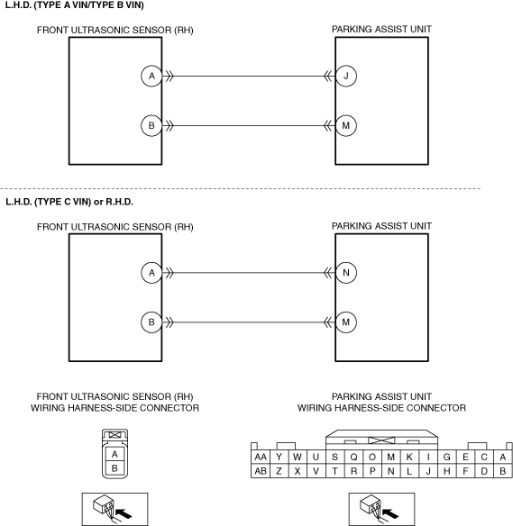
• L.H.D. (Type A VIN/Type B VIN)
-
? Front ultrasonic sensor (RH) terminal A—Parking assist unit terminal J
? Front ultrasonic sensor (RH) terminal B—Parking assist unit terminal M
• L.H.D. (Type C VIN) or R.H.D.
-
? Front ultrasonic sensor (RH) terminal A—Parking assist unit terminal N
? Front ultrasonic sensor (RH) terminal B—Parking assist unit terminal M
If there is a common connector:
• Determine the malfunctioning part by inspecting the common connector and the terminal for corrosion, damage, or pin disconnection, and the common wiring harness for a short to ground.
• Repair or replace the malfunctioning part.
If there is no common connector:
• Repair or replace the wiring harness which has a short to ground.
Go to Step 9.
|
|
No
|
Go to the next step.
|
|
7
|
INSPECT FRONT ULTRASONIC SENSOR (RH) CIRCUIT FOR SHORT TO POWER SUPPLY
• Verify that the front ultrasonic sensor (RH) and parking assist unit connectors are disconnected.
• Connect the negative battery terminal.
• Switch the ignition ON (engine off or on).
• Measure the voltage at the following terminals (wiring harness-side):
-
? Front ultrasonic sensor (RH) terminal A
? Front ultrasonic sensor (RH) terminal B
• Is the voltage 0 V?
|
Yes
|
Go to the next step.
|
|
No
|
Refer to the wiring diagram and verify whether or not there is a common connector between the following terminals:
• L.H.D. (Type A VIN/Type B VIN)
-
? Front ultrasonic sensor (RH) terminal A—Parking assist unit terminal J
? Front ultrasonic sensor (RH) terminal B—Parking assist unit terminal M
• L.H.D. (Type C VIN) or R.H.D.
-
? Front ultrasonic sensor (RH) terminal A—Parking assist unit terminal N
? Front ultrasonic sensor (RH) terminal B—Parking assist unit terminal M
If there is a common connector:
• Determine the malfunctioning part by inspecting the common connector and the terminal for corrosion, damage, or pin disconnection, and the common wiring harness for a short to power supply.
• Repair or replace the malfunctioning part.
If there is no common connector:
• Repair or replace the wiring harness which has a short to power supply.
Go to Step 9.
|
|
8
|
INSPECT FRONT ULTRASONIC SENSOR (RH) CIRCUIT FOR OPEN CIRCUIT
• Switch the ignition off.
• Disconnect the negative battery terminal.
• Verify that the front ultrasonic sensor (RH) and parking assist unit connectors are disconnected.
• Inspect for continuity between the following terminals (wiring harness-side):
-
? L.H.D. (Type A VIN/Type B VIN)
-
• Front ultrasonic sensor (RH) terminal A—Parking assist unit terminal J
• Front ultrasonic sensor (RH) terminal B—Parking assist unit terminal M
? L.H.D. (Type C VIN) or R.H.D.
-
• Front ultrasonic sensor (RH) terminal A—Parking assist unit terminal N
• Front ultrasonic sensor (RH) terminal B—Parking assist unit terminal M
• Is there continuity?
|
Yes
|
Go to the next step.
|
|
No
|
Refer to the wiring diagram and verify whether or not there is a common connector between the following terminals:
• L.H.D. (Type A VIN/Type B VIN)
-
? Front ultrasonic sensor (RH) terminal A—Parking assist unit terminal J
? Front ultrasonic sensor (RH) terminal B—Parking assist unit terminal M
• L.H.D. (Type C VIN) or R.H.D.
-
? Front ultrasonic sensor (RH) terminal A—Parking assist unit terminal N
? Front ultrasonic sensor (RH) terminal B—Parking assist unit terminal M
If there is a common connector:
• Determine the malfunctioning part by inspecting the common connector and the terminal for corrosion, damage, or pin disconnection, and the common wiring harness for an open circuit.
• Repair or replace the malfunctioning part.
If there is no common connector:
• Repair or replace the wiring harness which has an open circuit.
Go to the next step.
|
|
9
|
VERIFY THAT REPAIRS HAVE BEEN COMPLETED
• Always reconnect all disconnected connectors.
• Connect the negative battery terminal.
• Clear the DTC for the parking assist unit using the M-MDS.
• Retrieve the parking assist unit DTCs using the M-MDS.
• Is the same DTC displayed?
|
Yes
|
Repeat the inspection from Step 1.
• If the malfunction recurs, replace the parking assist unit.
Go to the next step.
|
|
No
|
Go to the next step.
|
|
10
|
VERIFY IF OTHER DTCs DISPLAYED
• Are any other DTCs displayed?
|
Yes
|
Repair or replace the malfunctioning part according to the applicable DTC troubleshooting.
|
|
No
|
DTC troubleshooting completed.
|