|
1
|
VERIFY THAT OPERATION INDICATOR LIGHT TURNS ON WHEN REMOTE TRANSMITTER BUTTON IS USED
• Does the operation indicator light turn on?
|
Yes
|
Go to Step 4.
|
|
No
|
Go to the next step.
|
|
2
|
VERIFY IF PROBLEM IS DUE TO REMOTE TRANSMITTER POWER SAVING FUNCTION
• Turn off the power saving function.
• Does the operation indicator light turn on?
|
Yes
|
Perform the repair completion verification.
|
|
No
|
Go to the next step.
|
|
3
|
VERIFY BATTERY USED FOR REMOTE TRANSMITTER
• Is any of the following conditions met?
-
? Battery other than CR2025 is used (With remote transmitter type A)
? Battery other than CR2032 is used (With remote transmitter type B)
? Battery is inserted in opposite direction
? Battery voltage is low
|
Yes
|
Replace the remote transmitter battery and perform the repair completion verification.
|
|
No
|
Replace the remote transmitter and perform the repair completion verification.
|
|
4
|
DETERMINE IF MALFUNCTION CAUSE IS DOOR LOCK
• Refer to “door lock does not operate” symptom troubleshooting and perform the inspection.
• Is the advanced keyless entry system operating normally?
|
Yes
|
Troubleshooting completed. (Explain the contents of the servicing to the customer.)
|
|
No
|
Go to the next step.
|
|
5
|
INSPECT ROOM FUSE CONDITION
• Is the fuse (ROOM fuse) normal?
|
Yes
|
Go to the next step.
|
|
No
|
• If the fuse installation is poor:
-
? Install the ROOM fuse properly.
• If the fuse is blown:
-
? Refer to the wiring diagram and verify whether or not there is a common connector between fuse and LF control unit terminal B.
If there is a common connector:
-
• Determine the malfunctioning part by inspecting the common connector and the terminal for corrosion, damage, or pin disconnection, and the common wiring harness for a short to ground.
• Repair or replace the malfunctioning part.
If there is no common connector:
-
• Repair or replace the wiring harness which has a short to ground.
• Replace the fuse.
• If the fuse is damaged:
-
? Replace the fuse.
Go to Step 21.
|
|
6
|
INSPECT REMOTE TRANSMITTER BATTERY POWER
• Inspect the battery power of the remote transmitter.
• Does the KEY indicator light (green) flash for approx. 30 s?
|
Yes
|
-
Note
-
• If the KEY indicator light (green) flashes for approx. 30 s, the battery power of the remote transmitter is low.
Replace the remote transmitter battery and go to Step 21.
|
|
No
|
Go to the next step.
|
|
7
|
VERIFY IF MALFUNCTION CAUSE IS OPERATION OTHER THAN OPERATION PERMISSION CONDITION
• Verify the advanced keyless operation by operating each request switch and the liftgate opener switch with all the following conditions met.
-
? All doors and liftgate closed
? Ignition switched off (LOCK)
? Remote transmitter is within reception area (80 cm radius from driver's door, front passenger's door, and liftgate)
• Is the advanced keyless entry system operating normally?
|
Yes
|
System is normal. (Explain to customer about operation range of advanced keyless entry system)
|
|
No
|
Go to the next step.
|
|
8
|
VERIFY MALFUNCTION SYMPTOM
• Does the liftgate open using the liftgate opener switch operation?
|
Yes
|
Go to Step 12.
|
|
No
|
Go to the next step.
|
|
9
|
DETERMINE IF MALFUNCTION CAUSE IS LIFTGATE OPENER SWITCH
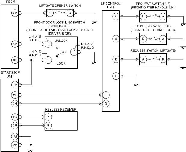
• Measure the voltage at rear body control module (RBCM) terminal 4M.
• Is the voltage normal?
Specification
-
Liftgate opener switch pressed: 1.0 or less
Except above: 4.5 V
|
Yes
|
Go to Step 21.
|
|
No
|
Go to the next step.
|
|
10
|
INSPECT IF MALFUNCTION CAUSE IS OPEN CIRCUIT IN WIRING HARNESS BETWEEN REAR BODY CONTROL MODULE (RBCM) AND LIFTGATE OPENER SWITCH
• Disconnect the negative battery terminal.
• Disconnect the rear body control module (RBCM) and liftgate opener switch connector.
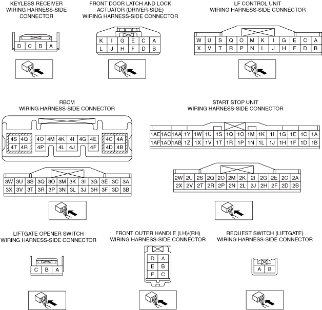
• Inspect for continuity between the following terminals (vehicle wiring harness).
-
? Liftgate opener switch terminal C and rear body control module (RBCM) terminal 4M
• Is there continuity?
|
Yes
|
Go to the next step.
|
|
No
|
• Repair or replace the wiring harness for an open circuit.
• After repair procedure, go to Step 21.
|
|
11
|
INSPECT IF MALFUNCTION CAUSE IS OPEN CIRCUIT OR POOR GROUND IN WIRING HARNESS BETWEEN LIFTGATE OPENER SWITCH AND GROUND
• Verify that the liftgate opener switch connector is disconnected.
• Inspect for continuity between the following terminals (vehicle wiring harness).
-
? Liftgate opener switch terminal A and ground
• Is there continuity?
|
Yes
|
• Inspect the liftgate opener switch. If there is any malfunction, replace it.
• If the liftgate opener switch inspection is normal, inspect or repair the following:
-
? Liftgate latch and actuator
• After repair procedure, go to Step 21.
|
|
No
|
• Repair or replace the wiring harness for an open circuit or poor ground.
• After repair, go to Step 21.
|
|
12
|
VERIFY MALFUNCTION SYMPTOM
• Connect the negative battery terminal.
• Verify the lock/unlock operation for all doors and liftgate using the request switch operation.
• Is door locked/unlocked?
|
Yes
|
Go to Step 21.
|
|
No
|
Go to the next step.
|
|
13
|
INSPECT IF MALFUNCTION CAUSE IS OPEN CIRCUIT IN WIRING HARNESS BETWEEN START STOP UNIT AND DOOR LOCK LINK SWITCH (DRIVER-SIDE)
• Disconnect the negative battery terminal.
• Disconnect the start stop unit and the front door latch and lock actuator (driver-side) connector.
• Inspect for continuity between the following terminals (vehicle wiring harness).
-
? Start stop unit terminal 1P and front door lock link switch terminal D (L.H.D.)/J (R.H.D.)
• Is there continuity?
|
Yes
|
Go to the next step.
|
|
No
|
• Repair or replace the wiring harness for an open circuit.
• After repair procedure, go to Step 21.
|
|
14
|
INSPECT IF MALFUNCTION CAUSE IS SHORT TO GROUND IN WIRING HARNESS BETWEEN START STOP UNIT AND DOOR LOCK LINK SWITCH (DRIVER-SIDE)
• Verify that the start stop unit connector is disconnected.
• Inspect for continuity between the following wiring harness terminals (vehicle wiring harness side) and body ground.
-
? Start stop unit terminal 1P and ground
• Is there continuity?
|
Yes
|
• Repair or replace the wiring harness for short to ground circuit.
• After repair procedure, go to Step 21.
|
|
No
|
Go to the next step.
|
|
15
|
INSPECT IF MALFUNCTION CAUSE IS OPEN CIRCUIT OR POOR GROUND IN WIRING HARNESS BETWEEN DOOR LOCK LINK SWITCH (DRIVER-SIDE) AND GROUND
• Verify that the front door latch and lock actuator (driver-side) connector is disconnected.
• Inspect for continuity between the following terminals (vehicle wiring harness).
-
? Front door latch and lock actuator (driver-side) terminal J (L.H.D.)/D (R.H.D.) and ground
• Is there continuity?
|
Yes
|
Go to the next step.
|
|
No
|
• Repair or replace the wiring harness for an open circuit or poor ground.
• After repair, go to Step 21.
|
|
16
|
INSPECT IF MALFUNCTION CAUSE IS OPEN CIRCUIT OR POOR GROUND IN WIRING HARNESS BETWEEN START STOP UNIT AND GROUND
• Verify that the start stop unit connector is disconnected.
• Inspect for continuity between the following terminals (vehicle wiring harness).
-
? Start stop unit terminal 1AF and ground
? Start stop unit terminal 2B and ground
• Is there continuity?
|
Yes
|
Go to the next step.
|
|
No
|
• Repair or replace the wiring harness for an open circuit or poor ground.
• After repair, go to Step 21.
|
|
17
|
INSPECT IF MALFUNCTION CAUSE IS OPEN CIRCUIT IN WIRING HARNESS BETWEEN REQUEST SWITCH AND LF CONTROL UNIT
• Disconnect the LF control unit and request switch connector.
• Inspect for continuity between the following terminals (vehicle wiring harness).
-
? Request switch (LF) terminal D and LF control unit terminal C
? Request switch (RF) terminal D and LF control unit terminal A
? Request switch (liftgate) terminal A and LF control unit terminal E
• Is there continuity?
|
Yes
|
Go to the next step.
|
|
No
|
• Repair or replace the wiring harness for an open circuit.
• After repair, go to Step 21.
|
|
18
|
INSPECT IF MALFUNCTION CAUSE IS OPEN CIRCUIT OR POOR GROUND IN WIRING HARNESS BETWEEN REQUEST SWITCH AND GROUND
• Verify that the request switch connectors are disconnected.
• Inspect for continuity between the following terminals (vehicle wiring harness).
-
? Request switch (LF) terminal A and ground
? Request switch (RF) terminal A and ground
? Request switch (liftgate) terminal B and ground
• Is there continuity?
|
Yes
|
Go to the next step.
|
|
No
|
• Repair or replace the wiring harness for an open circuit or poor ground.
• After repair, go to Step 21.
|
|
19
|
INSPECT IF MALFUNCTION CAUSE IS OPEN CIRCUIT IN WIRING HARNESS BETWEEN START STOP UNIT AND LF CONTROL UNIT
• Verify that the start stop unit and LF control unit connectors are disconnected.
• Inspect for continuity between the following terminals (vehicle wiring harness).
-
? Start stop unit terminal 2F and LF control unit terminal I
? Start stop unit terminal 2H and LF control unit terminal G
• Is there continuity?
|
Yes
|
Go to the next step.
|
|
No
|
• Repair or replace the wiring harness for an open circuit.
• After repair, go to Step 21.
|
|
20
|
INSPECT IF MALFUNCTION CAUSE IS OPEN CIRCUIT IN WIRING HARNESS BETWEEN START STOP UNIT AND KELESS RECEIVER
• Verify that the start stop unit connectors are disconnected.
• Disconnect the negative battery terminal.
• Disconnect the keyless receiver connector.
• Inspect for continuity between the following terminals (vehicle wiring harness).
-
? Start stop unit terminal 2Q and keyless receiver terminal A
? Start stop unit terminal 2R and keyless receiver terminal B
• Is there continuity?
|
Yes
|
Go to the next step.
|
|
No
|
• Repair or replace the wiring harness for an open circuit.
• After repair, go to the next step.
|
|
21
|
VERIFY IF MALFUNCTION CAUSE WAS CORRECTED
• Does the advanced keyless entry system operate normally?
|
Yes
|
Troubleshooting completed. (Explain the contents of the servicing to the customer.)
|
|
No
|
If the malfunction has not been resolved, repeat the inspection from Step 1.
|