|
1
|
VERIFY PERSONALIZATION FEATURES SETTING
• Operate the commander switch.
• Does the center display display?
|
Yes
|
Cause is that the center display setting was off. Explain to the customer that the screen setting was off.
|
|
No
|
Go to the next step.
|
|
2
|
VERIFY CONNECTIVITY MASTER UNIT (CMU) DTC
• Retrieve any DTCs using the M-MDS.
• Are any DTCs present?
|
Yes
|
Go to the applicable DTC inspection.
|
|
No
|
Go to the next step.
|
|
3
|
INSPECT CENTER DISPLAY CONNECTOR
• Switch the ignition off.
• Disconnect the negative battery terminal.
• Disconnect the center display connector.
• Inspect the connector engagement and connection condition and inspect the terminals for damage, deformation, corrosion, or disconnection.
• Is the connector normal?
|
Yes
|
Go to the next step.
|
|
No
|
Repair or replace the connector, then go to Step 8.
|
|
4
|
INSPECT CONNECTIVITY MASTER UNIT (CMU) CONNECTOR
• Disconnect the connectivity master unit (CMU) connector.
• Inspect the connector engagement and connection condition and inspect the terminals for damage, deformation, corrosion, or disconnection.
• Is the connector normal?
|
Yes
|
Go to the next step.
|
|
No
|
Repair or replace the connector, then go to Step 8.
|
|
5
|
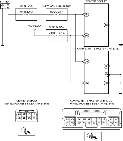
VERIFY IF MALFUNCTION CAUSE IS OPEN CIRCUIT IN WIRING HARNESS BETWEEN CENTER DISPLAY AND BODY GROUND
• Verify that the center display connector is disconnected.
• Inspect the wiring harness for continuity between center display terminal 1B and body ground (vehicle wiring harness side).
• Is there continuity?
|
Yes
|
Go to the next step.
|
|
No
|
• Refer to the wiring diagram and verify if there is a common connector between center display terminal 1B and body ground.
If there is a common connector:
-
? Inspect the common connector and terminals for corrosion, damage, or disconnection and the common wiring harnesses for an open circuit to determine the malfunctioning location.
? Repair or replace the malfunctioning location.
If there is no common connector:
-
? Repair or replace the wiring harness which has an open circuit.
• Go to Step 8.
|
|
6
|
VERIFY IF MALFUNCTION CAUSE IS OPEN CIRCUIT IN WIRING HARNESS BETWEEN CONNECTIVITY MASTER UNIT (CMU) AND BODY GROUND
• Verify that the connectivity master unit (CMU) connector is disconnected.
• Inspect the wiring harness for continuity between following connectivity master unit (CMU) terminals and body ground (vehicle wiring harness side).
-
? Connectivity master unit (CMU) terminal 2L
? Connectivity master unit (CMU) terminal 2D
? Connectivity master unit (CMU) terminal 2C
• Is there continuity?
|
Yes
|
Go to the next step.
|
|
No
|
• Refer to the wiring diagram and verify if there is a common connector between the following terminals.
-
? Connectivity master unit (CMU) terminal 2L and body ground
? Connectivity master unit (CMU) terminal 2D and body ground
? Connectivity master unit (CMU) terminal 2C and body ground
If there is a common connector:
-
? Inspect the common connector and terminals for corrosion, damage, or disconnection and the common wiring harnesses for an open circuit to determine the malfunctioning location.
? Repair or replace the malfunctioning location.
If there is no common connector:
-
? Repair or replace the wiring harness which has an open circuit.
• Go to Step 8.
|
|
7
|
VERIFY IF MALFUNCTION CAUSE IS CENTER DISPLAY
• Replace the center display.
• Connect all the connectors.
• Reconnect the negative battery terminal.
• Switch the ignition to ACC or ON (engine off or on).
• Is image output in the center display?
|
Yes
|
Go to the next step.
|
|
No
|
Replace the Connectivity master unit (CMU), then go to the next step.
|
|
8
|
VERIFY IF MALFUNCTION CAUSE IS CORRECTED
• Switch the ignition to ACC or ON (engine off or on).
• Select each mode by operating the center display or the commander switch.
• Is image in each mode output?
|
Yes
|
Troubleshooting completed (explain the contents of the servicing to the customer).
|
|
No
|
Verify the malfunction symptom in the symptom troubleshooting chart and perform the other applicable malfunction diagnosis.
|