|
1
|
VERIFY PCM DTC
• Using the M-MDS, perform the PCM DTC inspection.
• Are any DTCs present?
|
Yes
|
Go to applicable DTC inspection.
DTC troubleshooting completed, then go to the next step.
|
|
No
|
Go to the next step.
|
|
2
|
INSPECT BATTERY
• Is there any malfunction?
|
Yes
|
Charge or replace the battery, then go to Step7.
|
|
No
|
Go to the next step.
|
|
3
|
INSPECT GENERATOR
• Is there any malfunction?
|
Yes
|
Replace the generator, then go to Step7.
|
|
No
|
Go to the next step.
|
|
4
|
INSPECT FUSE CONDITION
• Is the fuse (C/U IG1 15A) normal?
|
Yes
|
Go to the next step.
|
|
No
|
• If the fuse is blown:
-
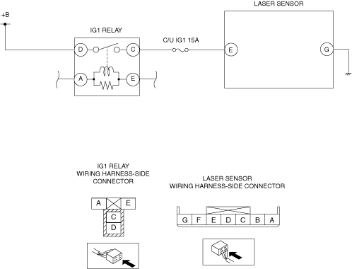
? Refer to the wiring diagram and verify whether or not there is a common connector between fuse and laser sensor terminal E.
If there is a common connector:
-
• Determine the malfunctioning part by inspecting the common connector and the terminal for corrosion, damage, or pin disconnection, and the common wiring harness for a short to ground.
• Repair or replace the malfunctioning part.
If there is no common connector:
-
• Repair or replace the wiring harness which has a short to ground.
• Replace the fuse.
• If the fuse is damaged:
-
? Replace the fuse.
Go to Step7.
|
|
5
|
INSPECT LASER SENSOR POWER SUPPLY CIRCUIT FOR OPEN CIRCUIT
• Switch the ignition OFF.
• Disconnect the laser sensor connector.
• Switch the ignition ON (engine off).
• Measure the voltage between laser sensor terminal E (wiring harness-side) and body ground.
• Is the voltage 10 V or more?
|
Yes
|
Go to the next Step.
|
|
No
|
Refer to the wiring diagram and verify whether or not there is a common connector between battery and laser sensor terminal E.
If there is a common connector:
• Determine the malfunctioning part by inspecting the common connector and the terminal for corrosion, damage, or pin disconnection, and the common wiring harness for an open circuit.
• Repair or replace the malfunctioning part.
If there is no common connector:
• Repair or replace the wiring harness which has an open circuit.
Go to Step7.
|
|
6
|
INSPECT LASER SENSOR GROUND CIRCUIT FOR OPEN CIRCUIT OR POOR GROUND
• Switch the ignition OFF.
• Disconnect the laser sensor connector.
• Inspect for continuity between laser sensor terminal G (wiring harness-side) and body ground.
• Is the resistance 0—1 ohm?
|
Yes
|
Go to the next step.
|
|
No
|
• If the open circuit could be detected in the wiring harness:
-
? Refer to the wiring diagram and verify whether or not there is a common connector between laser sensor terminal G and body ground.
If there is a common connector:
-
• Determine the malfunctioning part by inspecting the common connector and the terminal for corrosion, damage, or pin disconnection, and the common wiring harness for an open circuit.
• Repair or replace the malfunctioning part.
If there is no common connector:
-
• Repair or replace the wiring harness which has an open circuit.
? Go to the next step.
• If the resistance is out of specification:
-
? Refer to the wiring diagram and verify whether or not there is a common connector between laser sensor terminal G and body ground.
If there is a common connector:
-
• Determine the malfunctioning part by inspecting the common connector and the terminal for corrosion, damage, or pin disconnection, and the common wiring harness for an open circuit and a poor ground.
• Repair or replace the malfunctioning part.
If there is no common connector:
-
• Repair or replace the wiring harness which has a poor ground and a poor ground.
? Go to the next step.
|
|
7
|
VERIFY DTC TROUBLESHOOTING COMPLETED
• Using the M-MDS, clear the DTC from the laser sensor.
• Using the M-MDS, perform the laser sensor DTC inspection.
• Is the same DTC present?
|
Yes
|
Repeat the inspection from Step1.
If the malfunction recurs, replace the laser sensor, then go to the next step.
|
|
No
|
Go to the next step.
|
|
8
|
VERIFY NO DTC IS PRESENT
• Are any DTCs present?
|
Yes
|
Go to applicable DTC inspection.
|
|
No
|
DTC troubleshooting completed.
|