 |
ac9wzw00005222
SMART CITY BRAKE SUPPORT [REVERSE] (SCBS R) DOES NOT OPERATE/OPERATES INCORRECTLY [SMART CITY BRAKE SUPPORT [REVERSE] (SCBS R)]
id1503b1003600
Possible Causes
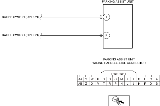
System Wiring Diagram
ac9wzw00005222
|
Diagnostic Procedure
|
Step |
Inspection |
Action |
|
|---|---|---|---|
|
1
|
VERIFY MALFUNCTION SYMPTOM
• Verify that the warning is displayed in the multi-information display when the selector lever is in the R position.
• Is the warning displayed?
|
Yes
|
Perform an inspection referring to "WARNING IS DISPLAYED IN MULTI-INFORMATION DISPLAY WHEN SELECTOR LEVER IS IN R POSITION".
|
|
No
|
Go to the next step.
|
||
|
2
|
VERIFY ALL SYSTEM DTCs
• Switch the ignition off.
• Switch the ignition ON (engine off or on) and wait for 10 s or more.
• Perform a CMDTC self-test using the M-MDS.
• Are any DTCs displayed?
|
Yes
|
Repair or replace the malfunctioning part according to the applicable DTC troubleshooting.
|
|
No
|
Go to the next step.
|
||
|
3
|
VERIFY IF ACCESSORY PART IS INSTALLED
• Verify if the following accessory accessories are installed to the vehicle.
• Is an accessory installed to the vehicle?
|
Yes
|
Go to the next step.
|
|
No
|
Go to Step 5.
|
||
|
4
|
VERIFY IF MALFUNCTIONING LOCATION IS ACCESSORY DEPENDING ON REPEATABILITY
• Switch the ignition off.
• Disconnect the negative battery terminal.
• Disconnect the connector of the following accessory part.
• Connect the negative battery terminal.
• Does the malfunction recur?
|
Yes
|
Go to the next step.
|
|
No
|
System is normal. (Explain to the customer that the malfunction occurred due to an accessory installed to the vehicle.)
|
||
|
5
|
VERIFY REAR BUMPER EXTERNAL APPEARANCE AND INSTALLATION CONDITION
• Verify that the rear bumper external appearance and installation condition.
• Are the rear bumper external appearance and installation condition normal?
|
Yes
|
Go to the next step.
|
|
No
|
Repair or replace the rear bumper.
|
||
|
6
|
VERIFY IF SYSTEM IS PURSUANT TO INHIBIT/LIMIT CONDITIONS
• Perform the malfunction diagnosis for the inhibit/limit conditions and verify if the system is pursuant to the inhibit/limit conditions.
• Is there anything pursuant to the inhibit/limit conditions?
|
Yes
|
Perform malfunction diagnosis for inhibit/limit conditions.
|
|
No
|
Go to the next step.
|
||
|
7
|
INSPECT PARKING ASSIST UNIT CONNECTOR CONDITION
• Switch the ignition off.
• Disconnect the negative battery terminal.
• Disconnect the parking assist unit connector.
• Inspect the connector engagement and connection condition and inspect the terminals for damage, deformation, corrosion, or disconnection.
• Is the connector normal?
|
Yes
|
Go to the next step.
|
|
No
|
Repair or replace the connector.
|
||
|
8
|
INSPECT ACCESSORY RELATED CIRCUIT FOR SHORT TO GROUND
• Verify that the parking assist unit connector is disconnected.
• Inspect for continuity between the following terminals (wiring harness-side) and body ground:
• Is there continuity?
|
Yes
|
Refer to the wiring diagram and verify if there is a common connector between the following circuits.
• Parking assist unit terminal T-related circuit
• Parking assist unit terminal R-related circuit
If there is a common connector:
• Determine the malfunctioning part by inspecting the common connector and the terminal for corrosion, damage, or pin disconnection, and the common wiring harness for a short to ground.
• Repair or replace the malfunctioning part.
If there is no common connector:
• Repair or replace the wiring harness which has a short to ground.
|
|
No
|
Replace the parking assist unit.
|
||
|
9
|
VERIFY MALFUNCTION CONDITION
• Verify with the customer the malfunction condition.
• At the time of the malfunction, did the customer drive the vehicle under any of the following conditions?
|
Yes
|
System is normal. (Explain to the customer that the system does not operate on steep slopes or if the steering angle is too wide.)
|
|
No
|
Go to the next step.
|
||
|
10
|
DETERMINE MALFUNCTION CAUSE
• Using the M-MDS, display the following PIDs for the parking assist unit.
• Does the selector lever position switch correctly in conjunction with the indicator?
|
Yes
|
Go to the next step.
|
|
No
|
Replace the TCM.
|
||
|
11
|
INSPECT REAR ULTRASONIC SENSOR
• Inspect the rear ultrasonic sensor.
• Is the rear ultrasonic sensor normal?
|
Yes
|
System is normal. (Explain the operating conditions and non-operating conditions of the system to the customer.)
|
|
No
|
Replace the malfunctioning rear ultrasonic sensor.
|
||