 |
ac9wzw00005777
DTC P0A94:00 [PCM (SKYACTIV-G 2.5T)]
id0102s8004400
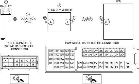
Without i-ELOOP
Details on DTCs
|
DESCRIPTION |
DC-DC converter: control circuit signal error |
|
|---|---|---|
|
DETECTION CONDITION
|
Determination conditions
|
• Internal malfunction signal from DC-DC converter via front body control module (FBCM) is received. (CAN/LIN communication).
• Input signal from the DC-DC converter limits the pressure increase time.
• Input signal from the DC-DC converter does not implement pressure increase after a pressure increase command to the DC-DC converter.
|
|
Preconditions
|
• Not applicable
|
|
|
Drive cycle
|
• 1
|
|
|
Self test type
|
• CMDTC self test
|
|
|
Sensor used
|
• Not applicable
|
|
|
FAIL-SAFE FUNCTION
|
• Inhibits engine-stop by operating the i-stop function.
|
|
|
VEHICLE STATUS WHEN DTCs ARE OUTPUT
|
• Flashes i-stop warning light (amber).
• A warning message is displayed in the display.
• Illuminates charging system warning light.
|
|
|
POSSIBLE CAUSE
|
• Front body control module (FBCM) malfunction
• Battery malfunction
• DC-DC converter connector or terminals malfunction
• Short to ground or open circuit in DC-DC converter power supply circuit
• PCM connector or terminals malfunction
• Short to ground in wiring harness between DC-DC converter terminal F and PCM terminal 2P
• Short to power supply in wiring harness between DC-DC converter terminal F and PCM terminal 2P
• Open circuit in wiring harness between DC-DC converter terminal F and PCM terminal 2P
• DC-DC converter malfunction
• PCM malfunction
|
|
System wiring diagram
ac9wzw00005777
|
Function explanation (DTC detection outline)
Repeatability verification procedure
PID item/simulation item used in diagnosis
Function inspection using M-MDS
|
STEP |
INSPECTION |
RESULTS |
ACTION |
|---|---|---|---|
|
1
|
PURPOSE: RECORD VEHICLE STATUS AT TIME OF DTC DETECTION TO UTILIZE WITH REPEATABILITY VERIFICATION
• Record the snapshot data on the repair order.
|
—
|
Go to the next step.
|
|
2
|
PURPOSE: VERIFY RELATED SERVICE INFORMATION AVAILABILITY
• Verify related Service Information availability.
• Is any related Service Information available?
|
Yes
|
Perform repair or diagnosis according to the available Service Information.
• If the vehicle is not repaired, go to the next step.
|
|
No
|
Go to the next step.
|
||
|
3
|
PURPOSE: VERIFY IF BATTERY VOLTAGE IS FALSELY RECOGNIZED BY DTC RELATED CAN OR LIN COMMUNICATION
• Switch the ignition off, then ON (engine off).
• Perform the PCM and front body control module (FBCM) DTC inspection using the M-MDS.
• Are DTCs related CAN or LIN communication recorded?
|
Yes
|
Repair or replace the malfunctioning part according to the applicable DTC troubleshooting.
Go to the next step.
|
|
No
|
Go to the next step.
|
||
|
4
|
PURPOSE: VERIFY IF THE CURRENT SENSOR IS MISIDENTIFYING MALFUNCTIONS DUE TO A FRONT BODY CONTROL MODULE (FBCM) MALFUNCTION
• Perform the front body control module (FBCM) DTC inspection using the M-MDS.
• Are any DTCs present?
|
Yes
|
Repair or replace the malfunctioning part according to the applicable DTC troubleshooting.
Go to the troubleshooting procedure to perform the procedure from Step 1.
|
|
No
|
Go to the troubleshooting procedure to perform the procedure from Step 1.
|
Troubleshooting diagnostic procedure
Diagnostic Procedure
|
STEP |
INSPECTION |
RESULTS |
ACTION |
|---|---|---|---|
|
1
|
PURPOSE: INSPECT BATTERY
• Switch the ignition off.
• Inspect the battery.
(See BATTERY INSPECTION.)
• Is there any malfunction?
|
Yes
|
Recharge or replace the battery, then go to Step 8.
(See BATTERY RECHARGING.)
(See BATTERY REMOVAL/INSTALLATION.)
|
|
No
|
Go to the next step.
|
||
|
2
|
PURPOSE: INSPECT DC-DC CONVERTER CONNECTOR CONDITION
• Switch the ignition off.
• Disconnect the DC-DC converter connector.
• Inspect for poor connection (such as damaged/pulled-out pins, corrosion).
• Is there any malfunction?
|
Yes
|
Repair or replace the connector and/or terminals, then go to Step 8.
|
|
No
|
Go to the next step.
|
||
|
3
|
PURPOSE: INSPECT DC-DC CONVERTER POWER SUPPLY CIRCUIT FOR SHORT TO GROUND OR OPEN CIRCUIT
• Verify that the DC-DC converter connector is disconnected.
• Measure the voltage at the DC-DC converter terminal L (wiring harness-side).
• Is the voltage B+?
|
Yes
|
Go to the next step.
|
|
No
|
Inspect the DCDC1 50 A fuse.
• If the fuse is blown:
• If the fuse is damaged:
• If the fuse is normal:
Go to Step 8.
|
||
|
4
|
PURPOSE: INSPECT PCM CONNECTOR CONDITION
• Disconnect the PCM connector.
• Inspect for poor connection (such as damaged/pulled-out pins, corrosion).
• Is there any malfunction?
|
Yes
|
Repair or replace the connector and/or terminals, then go to Step 8.
|
|
No
|
Go to the next step.
|
||
|
5
|
PURPOSE: INSPECT DC-DC CONVERTER SIGNAL CIRCUIT FOR SHORT TO GROUND
• Verify that the DC-DC converter and PCM connectors are disconnected.
• Inspect for continuity between DC-DC converter terminal F (wiring harness-side) and body ground.
• Is there continuity?
|
Yes
|
Refer to the wiring diagram and verify whether or not there is a common connector between DC-DC converter terminal F and PCM terminal 2P.
If there is a common connector:
• Determine the malfunctioning part by inspecting the common connector and the terminal for corrosion, damage, or pin disconnection, and the common wiring harness for a short to ground.
• Repair or replace the malfunctioning part.
If there is no common connector:
• Repair or replace the wiring harness which has a short to ground.
Go to Step 8.
|
|
No
|
Go to the next step.
|
||
|
6
|
PURPOSE: INSPECT DC-DC CONVERTER SIGNAL CIRCUIT FOR SHORT TO POWER SUPPLY
• Verify that the DC-DC converter and PCM connectors are disconnected.
• Switch the ignition ON (engine off).
• Measure the voltage at the DC-DC converter terminal F (wiring harness-side).
• Is the voltage 0 V?
|
Yes
|
Go to the next step.
|
|
No
|
Refer to the wiring diagram and verify whether or not there is a common connector between DC-DC converter terminal F and PCM terminal 2P.
If there is a common connector:
• Determine the malfunctioning part by inspecting the common connector and the terminal for corrosion, damage, or pin disconnection, and the common wiring harness for a short to power supply.
• Repair or replace the malfunctioning part.
If there is no common connector:
• Repair or replace the wiring harness which has a short to power supply.
Go to Step 8.
|
||
|
7
|
PURPOSE: INSPECT DC-DC CONVERTER SIGNAL CIRCUIT FOR OPEN CIRCUIT
• Verify that the DC-DC converter and PCM connectors are disconnected.
• Switch the ignition off.
• Inspect for continuity between DC-DC converter terminal F (wiring harness-side) and PCM terminal 2P (wiring harness-side).
• Is there continuity?
|
Yes
|
Go to the next step.
|
|
No
|
Refer to the wiring diagram and verify whether or not there is a common connector between DC-DC converter terminal F and PCM terminal 2P.
If there is a common connector:
• Determine the malfunctioning part by inspecting the common connector and the terminal for corrosion, damage, or pin disconnection, and the common wiring harness for an open circuit.
• Repair or replace the malfunctioning part.
If there is no common connector:
• Repair or replace the wiring harness which has an open circuit.
Go to the next step.
|
||
|
8
|
PURPOSE: VERIFY DTC TROUBLESHOOTING COMPLETED
• Always reconnect all disconnected connectors.
• Clear the DTC from the PCM memory using the M-MDS.
• Implement the repeatability verification procedure.
• Perform the DTC Reading Procedure.
• Is the same DTC present?
|
Yes
|
Replace the DC-DC converter, and then perform Step 8 again.
• If the malfunction recurs, replace the PCM.
Go to the next step.
|
|
No
|
Go to the next step.
|
||
|
9
|
PURPOSE: VERIFY AFTER REPAIR PROCEDURE
• Perform the “AFTER REPAIR PROCEDURE”.
• Are any DTCs present?
|
Yes
|
Go to the applicable DTC inspection.
|
|
No
|
DTC troubleshooting completed.
|
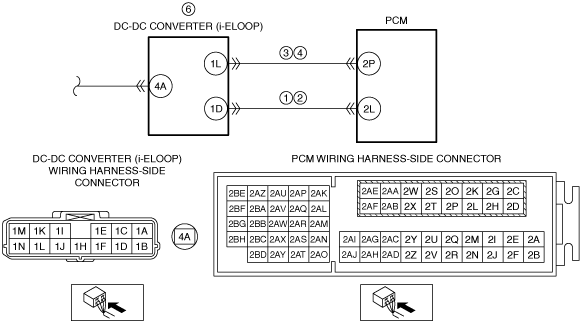
With i-ELOOP
Details on DTCs
|
DESCRIPTION |
DC-DC converter (i-ELOOP): control circuit signal error |
|
|---|---|---|
|
DETECTION CONDITION
|
Determination conditions
|
• The PCM receives a response signal from the DC-DC converter (i-ELOOP) which differs from the relay operation command voltage of the PCM.
|
|
Preconditions
|
• Not applicable
|
|
|
Drive cycle
|
• 1
|
|
|
Self test type
|
• CMDTC self test
|
|
|
Sensor used
|
• Not applicable
|
|
|
FAIL-SAFE FUNCTION
|
• Inhibits engine-stop by operating the i-stop function.
• Depending on the type of malfunction, any of the following controls may be implemented.
|
|
|
VEHICLE STATUS WHEN DTCs ARE OUTPUT
|
• Flashes i-stop warning light (amber).
• A warning message is displayed in the display.
• The following vehicle conditions differ depending on the type of malfunction
|
|
|
POSSIBLE CAUSE
|
• Connector or terminal malfunction of the following parts:
• Short to ground in wiring harness between the following terminals:
• Open circuit in wiring harness between the following terminals:
• DC-DC converter (i-ELOOP) malfunction
• PCM malfunction
|
|
System wiring diagram
ac9wzw00004517
|
Function explanation (DTC detection outline)
Repeatability verification procedure
PID item/simulation item used in diagnosis
Function inspection using M-MDS
|
STEP |
INSPECTION |
RESULTS |
ACTION |
|---|---|---|---|
|
1
|
PURPOSE: VERIFY RELATED SERVICE INFORMATION AVAILABILITY
• Verify related Service Information availability.
• Is any related Service Information available?
|
Yes
|
Perform repair or diagnosis according to the available Service Information.
• If the vehicle is not repaired, go to the next step.
|
|
No
|
Go to the next step.
|
||
|
2
|
PURPOSE: RECORD VEHICLE STATUS AT TIME OF DTC DETECTION TO UTILIZE WITH REPEATABILITY VERIFICATION
• Record the snapshot data on the repair order.
|
—
|
Go to the troubleshooting procedure to perform the procedure from Step 1.
|
Troubleshooting diagnostic procedure
|
STEP |
INSPECTION |
RESULTS |
ACTION |
|---|---|---|---|
|
1
|
PURPOSE: VERIFY IF SHORT TO GROUND IN EACH WIRING HARNESS AFFECTS DIAGNOSTIC RESULTS
• Switch the ignition off.
• Disconnect the connector of the following parts.
• Inspect for continuity between the following terminals (wiring harness-side) and body ground:
• Is there continuity?
|
Yes
|
Refer to the wiring diagram and verify whether or not there is a common connector between the following terminals:
• PCM terminal 2L—DC-DC converter (i-ELOOP) terminal 1D
If there is a common connector:
• Determine the malfunctioning part by inspecting the common connector and the terminal for corrosion, damage, or pin disconnection, and the common wiring harness for a short to ground.
• Repair or replace the malfunctioning part.
If there is no common connector:
• Repair or replace the wiring harness which has a short to ground.
Go to Step 7.
|
|
No
|
Go to the next step.
|
||
|
2
|
PURPOSE: VERIFY IF OPEN CIRCUIT IN EACH WIRING HARNESS AFFECTS DIAGNOSTIC RESULTS
• Verify that the DC-DC converter (i-ELOOP) and PCM connectors are disconnected.
• Inspect for continuity between the following terminals (wiring harness-side):
• Is there continuity?
|
Yes
|
Go to the next step.
|
|
No
|
Refer to the wiring diagram and verify whether or not there is a common connector between the following terminals:
• PCM terminal 2L—DC-DC converter (i-ELOOP) terminal 1D
If there is a common connector:
• Determine the malfunctioning part by inspecting the common connector and the terminal for corrosion, damage, or pin disconnection, and the common wiring harness for an open circuit.
• Repair or replace the malfunctioning part.
If there is no common connector:
• Repair or replace the wiring harness which has an open circuit.
Go to Step 7.
|
||
|
3
|
PURPOSE: VERIFY IF SHORT TO GROUND IN EACH WIRING HARNESS AFFECTS DIAGNOSTIC RESULTS
• Verify that the DC-DC converter (i-ELOOP) and PCM connectors are disconnected.
• Inspect for continuity between the following terminals (wiring harness-side) and body ground:
• Is there continuity?
|
Yes
|
Refer to the wiring diagram and verify whether or not there is a common connector between the following terminals:
• PCM terminal 2P—DC-DC converter (i-ELOOP) terminal 1L
If there is a common connector:
• Determine the malfunctioning part by inspecting the common connector and the terminal for corrosion, damage, or pin disconnection, and the common wiring harness for a short to ground.
• Repair or replace the malfunctioning part.
If there is no common connector:
• Repair or replace the wiring harness which has a short to ground.
Go to Step 7.
|
|
No
|
Go to the next step.
|
||
|
4
|
PURPOSE: VERIFY IF OPEN CIRCUIT IN EACH WIRING HARNESS AFFECTS DIAGNOSTIC RESULTS
• Verify that the DC-DC converter (i-ELOOP) and PCM connectors are disconnected.
• Inspect for continuity between the following terminals (wiring harness-side):
• Is there continuity?
|
Yes
|
Go to the next step.
|
|
No
|
Refer to the wiring diagram and verify whether or not there is a common connector between the following terminals:
• PCM terminal 2P—DC-DC converter (i-ELOOP) terminal 1L
If there is a common connector:
• Determine the malfunctioning part by inspecting the common connector and the terminal for corrosion, damage, or pin disconnection, and the common wiring harness for an open circuit.
• Repair or replace the malfunctioning part.
If there is no common connector:
• Repair or replace the wiring harness which has an open circuit.
Go to Step 7.
|
||
|
5
|
PURPOSE: VERIFY IF MALFUNCTION OCCURRING IS CAUSED BY WIRING HARNESS/CONNECTOR LOSS
• Have all the wiring harnesses/connectors which can be considered the cause of DTC P0A94:00 been inspected?
|
Yes
|
Go to the next step.
|
|
No
|
Inspect all the related wiring harnesses/connectors.
• If there is any malfunction:
• If there is no malfunction:
|
||
|
6
|
PURPOSE: VERIFY DC-DC CONVERTER (i-ELOOP) REPLACEMENT RECORD
• Is the DC-DC converter (i-ELOOP) being replaced within the troubleshooting diagnostic procedure this time?
|
Yes
|
Replace the PCM.
Go to the next step.
|
|
No
|
Replace the DC-DC converter (i-ELOOP).
Go to the next step.
|
||
|
7
|
PURPOSE: VERIFICATION OF VEHICLE REPAIR COMPLETION
• Always reconnect all disconnected connectors.
• Clear the DTC from the PCM memory using the M-MDS.
• Implement the repeatability verification procedure.
• Perform the DTC Reading Procedure.
• Is the same DTC present?
|
Yes
|
Repeat the inspection from Step 5.
|
|
No
|
Go to the next step.
|
||
|
8
|
PURPOSE: VERIFY IF THERE IS ANY OTHER MALFUNCTION
• Is any other DTC or pending code stored?
|
Yes
|
Go to the applicable DTC inspection.
|
|
No
|
DTC troubleshooting completed.
|