 |
ac9wzw00005778
DTC P0A8D:00 [PCM (SKYACTIV-G 2.5T)]
id0102s8009400
Without i-ELOOP
Details on DTCs
|
DESCRIPTION |
Power supply system circuit low input |
|
|---|---|---|
|
DETECTION CONDITION
|
Determination conditions
|
• Any one of the following conditions is met:
|
|
Preconditions
|
• Not applicable.
|
|
|
Drive cycle
|
• 1
|
|
|
Self test type
|
• CMDTC self test
|
|
|
Sensor used
|
• Current sensor
|
|
|
FAIL-SAFE FUNCTION
|
• Inhibits engine-stop by operating the i-stop function.
|
|
|
VEHICLE STATUS WHEN DTCs ARE OUTPUT
|
• Flashes i-stop warning light (amber).
• A warning message is displayed in the display.
• Illuminates master warning light.
• The engine may not start, it may stall, or it may not restart by i-stop due to a battery voltage decrease.
|
|
|
POSSIBLE CAUSE
|
• Battery performance decrease or malfunction
• Connector or terminal malfunction of the following parts:
• Malfunction in the following fuses:
• Short to ground in wiring harness between the following terminals:
• Open circuit in wiring harness between the following terminals:
• Current sensor malfunction
• Front body control module (FBCM) malfunction
• DC-DC converter malfunction
• PCM malfunction
|
|
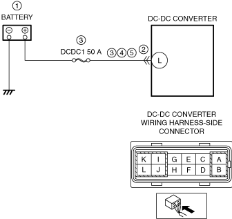
System wiring diagram
ac9wzw00005778
|
Function explanation (DTC detection outline)
Repeatability verification procedure
PID item/simulation item used in diagnosis
PID/DATA monitor item table
|
Item |
Definition |
Unit |
Condition/Specification |
|---|---|---|---|
|
BATT_CUR
|
Battery charge/discharge current
|
A
|
• Displays battery charge/discharge current value
|
|
VPWR
|
Battery positive voltage
|
V
|
• Displays battery voltage
|
Function inspection using M-MDS
|
STEP |
INSPECTION |
RESULTS |
ACTION |
|---|---|---|---|
|
1
|
PURPOSE: RECORD VEHICLE STATUS AT TIME OF DTC DETECTION TO UTILIZE WITH REPEATABILITY VERIFICATION
• Record the snapshot data on the repair order.
|
—
|
Go to the next step.
|
|
2
|
PURPOSE: VERIFY RELATED SERVICE INFORMATION AVAILABILITY
• Verify related Service Information availability.
• Is any related Service Information available?
|
Yes
|
Perform repair or diagnosis according to the available Service Information.
• If the vehicle is not repaired, go to the next step.
|
|
No
|
Go to the next step.
|
||
|
3
|
PURPOSE: VERIFY IF POWER SUPPLY IS AFFECTED BY DTC RELATED TO DC-DC CONVERTER
• Switch the ignition off, then ON (engine off).
• Perform the Pending Trouble Code Access Procedure and DTC Reading Procedure.
• Are DTCs related DC-DC converter recorded?
|
Yes
|
Go to the applicable PENDING CODE or DTC inspection.
Go to the next step.
|
|
No
|
Go to the next step.
|
||
|
4
|
PURPOSE: VERIFY IF BATTERY VOLTAGE IS FALSELY RECOGNIZED BY DTC RELATED CURRENT SENSOR
• Perform the Pending Trouble Code Access Procedure and DTC Reading Procedure.
• Is the PENDING CODE/DTC P058A:00 also present?
|
Yes
|
Go to the applicable PENDING CODE or DTC inspection.
Go to the next step.
|
|
No
|
Go to the next step.
|
||
|
5
|
PURPOSE: VERIFY IF BATTERY VOLTAGE IS FALSELY RECOGNIZED BY DTC RELATED CAN OR LIN COMMUNICATION
• Perform the PCM and front body control module (FBCM) DTC inspection using the M-MDS.
• Are DTCs related CAN or LIN communication recorded?
|
Yes
|
Repair or replace the malfunctioning part according to the applicable DTC troubleshooting.
Go to the troubleshooting procedure to perform the procedure from Step 1.
|
|
No
|
Go to the troubleshooting procedure to perform the procedure from Step 1.
|
Troubleshooting diagnostic procedure
|
STEP |
INSPECTION |
RESULTS |
ACTION |
|---|---|---|---|
|
1
|
PURPOSE: DETERMINE INTEGRITY OF BATTERY
• Inspect the battery.
(See BATTERY INSPECTION.)
• Is there any malfunction?
|
Yes
|
Replace the battery, then go to Step 6.
(See BATTERY REMOVAL/INSTALLATION.)
|
|
No
|
Go to the next step.
|
||
|
2
|
PURPOSE: VERIFY IF CONNECTOR DAMAGE OF EACH PART AFFECTS DIAGNOSTIC RESULTS
• Switch the ignition off.
• Disconnect the connector of the following parts.
• Inspect for poor connection (such as damaged/pulled-out pins, corrosion).
• Is there any malfunction?
|
Yes
|
Repair or replace the connector and/or terminals, then go to Step 6.
|
|
No
|
Go to the next step.
|
||
|
3
|
PURPOSE: INSPECT FUSE
• Remove the following fuses:
• Inspect the following fuses:
• Are all the fuses normal?
|
Yes
|
Install all the removed fuses, then go to the next step.
|
|
No
|
If the fuse is blown:
• Refer to the wiring diagram and verify whether or not there is a common connector between the following terminals:
If there is a common connector:
If there is no common connector:
If the fuse is damaged:
• Replace the fuse.
Go to Step 6.
|
||
|
4
|
PURPOSE: VERIFY IF SHORT TO GROUND IN EACH WIRING HARNESS AFFECTS DIAGNOSTIC RESULTS
• Verify that the battery, current sensor, PCM and DC-DC converter connectors are disconnected.
• Inspect for continuity between the following terminals (wiring harness-side) and body ground:
• Is there continuity?
|
Yes
|
Refer to the wiring diagram and verify whether or not there is a common connector between the following terminals:
• Battery positive terminal—DC-DC converter terminal L
If there is a common connector:
• Determine the malfunctioning part by inspecting the common connector and the terminal for corrosion, damage, or pin disconnection, and the common wiring harness for a short to ground.
• Repair or replace the malfunctioning part.
If there is no common connector:
• Repair or replace the wiring harness which has a short to ground.
Go to Step 6.
|
|
No
|
Go to the next step.
|
||
|
5
|
PURPOSE: VERIFY IF OPEN CIRCUIT IN EACH WIRING HARNESS AFFECTS DIAGNOSTIC RESULTS
• Verify that the battery, current sensor, PCM and DC-DC converter connectors are disconnected.
• Inspect for continuity between the following terminals (wiring harness-side):
• Is there continuity?
|
Yes
|
Go to the next step.
|
|
No
|
Refer to the wiring diagram and verify whether or not there is a common connector between the following terminals:
• Battery positive terminal—DC-DC converter terminal L
If there is a common connector:
• Determine the malfunctioning part by inspecting the common connector and the terminal for corrosion, damage, or pin disconnection, and the common wiring harness for an open circuit.
• Repair or replace the malfunctioning part.
If there is no common connector:
• Repair or replace the wiring harness which has an open circuit.
Go to the next step.
|
||
|
6
|
PURPOSE: VERIFICATION OF VEHICLE REPAIR COMPLETION
• Always reconnect all disconnected connectors.
• Clear the DTC from the PCM memory using the M-MDS.
• Implement the repeatability verification procedure.
• Perform the DTC Reading Procedure.
• Is the same DTC present?
|
Yes
|
Repeat the inspection from Step 1.
• If the malfunction recurs, replace the PCM.
Go to the next step.
|
|
No
|
Go to the next step.
|
||
|
7
|
PURPOSE: VERIFY IF THERE IS ANY OTHER MALFUNCTION
• Is any other DTC or pending code stored?
|
Yes
|
Go to the applicable DTC inspection.
|
|
No
|
DTC troubleshooting completed.
|
With i-ELOOP
Details on DTCs
|
DESCRIPTION |
Power supply system circuit low input |
|
|---|---|---|
|
DETECTION CONDITION
|
Determination conditions
|
• Any one of the following conditions is met:
|
|
Preconditions
|
• Not applicable.
|
|
|
Drive cycle
|
• 1
|
|
|
Self test type
|
• CMDTC self test
|
|
|
Sensor used
|
• Current sensor
|
|
|
FAIL-SAFE FUNCTION
|
• Inhibits engine-stop by operating the i-stop function.
• Inhibits the i-ELOOP control.
|
|
|
VEHICLE STATUS WHEN DTCs ARE OUTPUT
|
• Flashes i-stop warning light (amber).
• Illuminates the master warning light. (without multi-information display)
• A warning message is displayed in the display.
• The engine may not start, it may stall, or it may not restart by i-stop due to a battery voltage decrease.
|
|
|
POSSIBLE CAUSE
|
• Battery performance decrease or malfunction
• Connector or terminal malfunction of the following parts:
• Malfunction in the following fuses:
• Short to ground in wiring harness between the following terminals:
• Open circuit in wiring harness between the following terminals:
• Current sensor malfunction
• Front body control module (FBCM) malfunction
• DC-DC converter (i-ELOOP) malfunction
• PCM malfunction
|
|
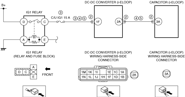
System wiring diagram
ac9wzw00004518
|
Function explanation (DTC detection outline)
Repeatability verification procedure
PID item/simulation item used in diagnosis
PID/DATA monitor item table
|
Item |
Definition |
Unit |
Condition/Specification |
|---|---|---|---|
|
BATT_CUR
|
Battery charge/discharge current
|
A
|
• Displays battery charge/discharge current value
Ignition switched ON (engine off)
Idle (after warm up)
Racing (Engine speed is 2,000 rpm)
|
|
VPWR
|
Battery positive voltage
|
V
|
• Displays battery voltage
|
Function inspection using M-MDS
|
STEP |
INSPECTION |
RESULTS |
ACTION |
|---|---|---|---|
|
1
|
PURPOSE: RECORD VEHICLE STATUS AT TIME OF DTC DETECTION TO UTILIZE WITH REPEATABILITY VERIFICATION
• Record the snapshot data on the repair order.
|
—
|
Go to the next step.
|
|
2
|
PURPOSE: VERIFY RELATED SERVICE INFORMATION AVAILABILITY
• Verify related Service Information availability.
• Is any related Service Information available?
|
Yes
|
Perform repair or diagnosis according to the available Service Information.
• If the vehicle is not repaired, go to the next step.
|
|
No
|
Go to the next step.
|
||
|
3
|
PURPOSE: VERIFY IF POWER SUPPLY IS AFFECTED BY DTC RELATED TO DC-DC CONVERTER (i-ELOOP)
• Switch the ignition off, then ON (engine off).
• Perform the DC-DC converter (i-ELOOP) DTC inspection using the M-MDS.
(See DTC INSPECTION [i-ELOOP].)
• Are any DTCs present?
|
Yes
|
Repair or replace the malfunctioning part according to the applicable DTC troubleshooting.
(See DTC TABLE [i-ELOOP].)
Go to the next step.
|
|
No
|
Go to the next step.
|
||
|
4
|
PURPOSE: VERIFY IF BATTERY VOLTAGE IS FALSELY RECOGNIZED BY DTC RELATED CURRENT SENSOR
• Perform the Pending Trouble Code Access Procedure and DTC Reading Procedure.
• Is the PENDING CODE/DTC P058A:00 also present?
|
Yes
|
Go to the applicable PENDING CODE or DTC inspection.
Go to the next step.
|
|
No
|
Go to the next step.
|
||
|
5
|
PURPOSE: VERIFY IF BATTERY VOLTAGE IS FALSELY RECOGNIZED BY DTC RELATED CAN OR LIN COMMUNICATION
• Perform the PCM and front body control module (FBCM) DTC inspection using the M-MDS.
• Are DTCs related CAN or LIN communication recorded?
|
Yes
|
Repair or replace the malfunctioning part according to the applicable DTC troubleshooting.
Go to the troubleshooting procedure to perform the procedure from Step 1.
|
|
No
|
Go to the troubleshooting procedure to perform the procedure from Step 1.
|
Troubleshooting diagnostic procedure
|
STEP |
INSPECTION |
RESULTS |
ACTION |
|---|---|---|---|
|
1
|
PURPOSE: DETERMINE INTEGRITY OF BATTERY
• Inspect the battery.
(See BATTERY INSPECTION.)
• Is there any malfunction?
|
Yes
|
Replace the battery, then go to Step 6.
(See BATTERY REMOVAL/INSTALLATION.)
|
|
No
|
Go to the next step.
|
||
|
2
|
PURPOSE: VERIFY IF CONNECTOR DAMAGE OF EACH PART AFFECTS DIAGNOSTIC RESULTS
• Switch the ignition off.
• Remove the service plug.
• Disconnect the connector of the following parts.
• Inspect for poor connection (such as damaged/pulled-out pins, corrosion).
• Is there any malfunction?
|
Yes
|
Repair or replace the connector and/or terminals, then go to Step 6.
|
|
No
|
Go to the next step.
|
||
|
3
|
PURPOSE: INSPECT FUSE
• Remove the C/U IG1 15 A fuse.
• Inspect the C/U IG1 15 A fuse.
• Is there any malfunction?
|
Yes
|
If the fuse is blown:
• Refer to the wiring diagram and verify whether or not there is a common connector between IG1 relay terminal C and DC-DC converter (i-ELOOP) terminal 1F.
If there is a common connector:
If there is no common connector:
If the fuse is damaged:
• Replace the fuse.
Go to Step 6.
|
|
No
|
Reinstall the C/U IG1 15 A fuse, then go to the next step.
|
||
|
4
|
PURPOSE: VERIFY IF SHORT TO GROUND IN EACH WIRING HARNESS AFFECTS DIAGNOSTIC RESULTS
• Verify that the battery, current sensor, PCM, capacitor (i-ELOOP), and DC-DC converter (i-ELOOP) connectors are disconnected.
• Remove the IG1 relay.
(See RELAY LOCATION.)
• Inspect for continuity between the following terminals (wiring harness-side) and body ground:
• Is there continuity?
|
Yes
|
Refer to the wiring diagram and verify whether or not there is a common connector between the following terminals:
• IG1 relay terminal C—DC-DC converter (i-ELOOP) terminal 1F
• DC-DC converter (i-ELOOP) terminal 2A—Capacitor (i-ELOOP) terminal 3A
If there is a common connector:
• Determine the malfunctioning part by inspecting the common connector and the terminal for corrosion, damage, or pin disconnection, and the common wiring harness for a short to ground.
• Repair or replace the malfunctioning part.
If there is no common connector:
• Repair or replace the wiring harness which has a short to ground.
Go to Step 6.
|
|
No
|
Go to the next step.
|
||
|
5
|
PURPOSE: VERIFY IF OPEN CIRCUIT IN EACH WIRING HARNESS AFFECTS DIAGNOSTIC RESULTS
• IG1 relay is removed.
• Verify that the battery, current sensor, PCM, capacitor (i-ELOOP), and DC-DC converter (i-ELOOP) connectors are disconnected.
• Inspect for continuity between the following terminals (wiring harness-side):
• Is there continuity?
|
Yes
|
Go to the next step.
|
|
No
|
Refer to the wiring diagram and verify whether or not there is a common connector between the following terminals:
• IG1 relay terminal C—DC-DC converter (i-ELOOP) terminal 1F
• DC-DC converter (i-ELOOP) terminal 2A—Capacitor (i-ELOOP) terminal 3A
If there is a common connector:
• Determine the malfunctioning part by inspecting the common connector and the terminal for corrosion, damage, or pin disconnection, and the common wiring harness for an open circuit.
• Repair or replace the malfunctioning part.
If there is no common connector:
• Repair or replace the wiring harness which has an open circuit.
Go to the next step.
|
||
|
6
|
PURPOSE: VERIFICATION OF VEHICLE REPAIR COMPLETION
• Always reconnect all disconnected connectors.
• Reinstall the service plug.
• Clear the DTC from the PCM memory using the M-MDS.
• Implement the repeatability verification procedure.
• Perform the DTC Reading Procedure.
• Is the same DTC present?
|
Yes
|
Repeat the inspection from Step 1.
• If the malfunction recurs, replace the PCM.
Go to the next step.
|
|
No
|
Go to the next step.
|
||
|
7
|
PURPOSE: VERIFY IF THERE IS ANY OTHER MALFUNCTION
• Is any other DTC or pending code stored?
|
Yes
|
Go to the applicable DTC inspection.
|
|
No
|
DTC troubleshooting completed.
|