 |
ac9uuw00007859
DTC P2502:00 [PCM (SKYACTIV-G 2.5T)]
id0102s8709500
Details On DTCs (Without i-ELOOP)
|
DESCRIPTION |
Generator system: Malfunction in voltage generated by generator |
|
|---|---|---|
|
DETECTION CONDITION
|
Determination conditions
|
• The voltage generated by the generator is 17 V or higher and the battery voltage is 11 V or less for a continuous specified time.
|
|
Preconditions
|
• While engine is running
|
|
|
Malfunction determination period
|
• 5 s period
|
|
|
Drive cycle
|
• 1
|
|
|
Self test type
|
• CMDTC self test
|
|
|
Sensor used
|
• PCM
• Generator
|
|
|
FAIL-SAFE FUNCTION
|
• Inhibits engine-stop by operating the i-stop function. (With i-stop)
• Generator control is inhibited.
|
|
|
VEHICLE STATUS WHEN DTCs ARE OUTPUT
|
• Flash the i-stop warning light (amber). (With i-stop)
• A warning message is displayed in the display.
• Illuminates charging system warning light.
• If the vehicle continues to be driven while the DTC is detected the battery will be depleted.
• The following vehicle conditions differ depending on the type of malfunction:
|
|
|
POSSIBLE CAUSE
|
• Poor connection of the following parts:
• Connector or terminal malfunction of the following parts:
• Short to ground or open circuit in generator charge/discharge circuit
• Generator malfunction
• Battery malfunction
• PCM malfunction
|
|
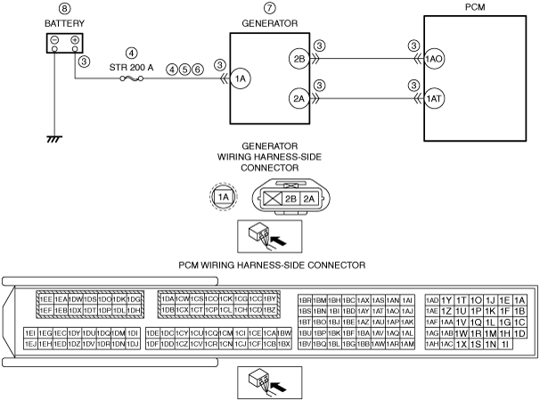
System Wiring Diagram (Without i-ELOOP)
ac9uuw00007859
|
Function Explanation (DTC Detection Outline) (Without i-ELOOP)
Repeatability Verification Procedure (Without i-ELOOP)
PID Item/Simulation Item Used In Diagnosis (Without i-ELOOP)
Function Inspection Using M-MDS (Without i-ELOOP)
|
STEP |
INSPECTION |
RESULTS |
ACTION |
|---|---|---|---|
|
1
|
PURPOSE: RECORD VEHICLE STATUS AT TIME OF DTC DETECTION TO UTILIZE WITH REPEATABILITY VERIFICATION
• Record the snapshot data on the repair order.
|
—
|
Go to the troubleshooting procedure to perform the procedure from Step 1.
|
Troubleshooting Diagnostic Procedure (Without i-ELOOP)
|
STEP |
INSPECTION |
RESULTS |
ACTION |
|---|---|---|---|
|
1
|
PURPOSE: VERIFY RELATED SERVICE INFORMATION AVAILABILITY
• Verify related Service Information availability.
• Is any related Service Information available?
|
Yes
|
Perform repair or diagnosis according to the available Service Information.
• If the vehicle is not repaired, go to the next step.
|
|
No
|
Go to the next step.
|
||
|
2
|
PURPOSE: VERIFY IF POOR CONNECTION OF EACH PART AFFECTS DIAGNOSTIC RESULTS
• Switch the ignition off.
• Inspect the connection condition (part installation condition, connector connection condition) for the following parts:
• Is the connection condition (part installation condition, connector connection condition) for each part normal?
|
Yes
|
Go to the next step.
|
|
No
|
Connect each part or the connector correctly, then go to Step 8.
|
||
|
3
|
PURPOSE: VERIFY IF CONNECTOR DAMAGE OF EACH PART AFFECTS DIAGNOSTIC RESULTS
• Disconnect the connector of the following parts.
• Inspect for poor connection (such as damaged/pulled-out pins, corrosion).
• Is there any malfunction?
|
Yes
|
Repair or replace the connector and/or terminals, then go to Step 8.
|
|
No
|
Go to the next step.
|
||
|
4
|
PURPOSE: INSPECT FUSE
• Remove the STR 200 A fuse.
• Inspect the STR 200 A fuse.
• Is there any malfunction?
|
Yes
|
If the fuse is blown:
• Refer to the wiring diagram and verify whether or not there is a common connector between battery positive terminal and generator terminal 1A.
If there is a common connector:
If there is no common connector:
If the fuse is damaged:
• Replace the fuse.
Go to Step 8.
|
|
No
|
Reinstall the STR 200 A fuse, then go to the next step.
|
||
|
5
|
PURPOSE: VERIFY IF SHORT TO GROUND IN GENERATOR CHARGE/DISCHARGE CIRCUIT AFFECTS DIAGNOSTIC RESULTS
• Verify that the battery, generator and PCM connectors are disconnected.
• Inspect for continuity between generator terminal 1A (wiring harness-side) and body ground.
• Is there continuity?
|
Yes
|
Refer to the wiring diagram and verify whether or not there is a common connector between battery positive terminal and generator terminal 1A.
If there is a common connector:
• Determine the malfunctioning part by inspecting the common connector and the terminal for corrosion, damage, or pin disconnection, and the common wiring harness for a short to ground.
• Repair or replace the malfunctioning part.
If there is no common connector:
• Repair or replace the wiring harness which has a short to ground.
Go to Step 8.
|
|
No
|
Go to the next step.
|
||
|
6
|
PURPOSE: VERIFY IF OPEN CIRCUIT IN GENERATOR CHARGE/DISCHARGE CIRCUIT AFFECTS DIAGNOSTIC RESULTS
• Verify that the battery, generator and PCM connectors are disconnected.
• Inspect for continuity between battery positive terminal (wiring harness-side) and generator terminal 1A (wiring harness-side).
• Is there continuity?
|
Yes
|
Go to the next step.
|
|
No
|
Refer to the wiring diagram and verify whether or not there is a common connector between battery positive terminal and generator terminal 1A.
If there is a common connector:
• Determine the malfunctioning part by inspecting the common connector and the terminal for corrosion, damage, or pin disconnection, and the common wiring harness for an open circuit.
• Repair or replace the malfunctioning part.
If there is no common connector:
• Repair or replace the wiring harness which has an open circuit.
Go to Step 8.
|
||
|
7
|
PURPOSE: DETERMINE INTEGRITY OF GENERATOR
• Inspect the generator.
• Is there any malfunction?
|
Yes
|
Replace the generator, then go to the next step.
|
|
No
|
Go to the next step.
|
||
|
8
|
PURPOSE: VERIFY CONDITIONS OF BATTERY
• Inspect the battery.
(See BATTERY INSPECTION.)
|
—
|
Follow the inspection instructions, then go to the next step.
|
|
9
|
PURPOSE: VERIFICATION OF VEHICLE REPAIR COMPLETION
• Always reconnect all disconnected connectors.
• Clear the DTC from the PCM memory using the M-MDS.
• Implement the repeatability verification procedure.
• Perform the DTC Reading Procedure.
• Is the same DTC present?
|
Yes
|
Repeat the inspection from Step 1.
• If the malfunction recurs, replace the PCM.
Go to the next step.
|
|
No
|
Go to the next step.
|
||
|
10
|
PURPOSE: VERIFY IF THERE IS ANY OTHER MALFUNCTION
• Is any other DTC or pending code stored?
|
Yes
|
Go to the applicable DTC inspection.
|
|
No
|
DTC troubleshooting completed.
|
Details On DTCs (With i-ELOOP)
|
DESCRIPTION |
Generator system: Malfunction in voltage generated by generator |
|
|---|---|---|
|
DETECTION CONDITION
|
Determination conditions
|
• Battery voltage is 11 V or less and condition in which current sensor detects battery charging for specified period continues
|
|
Preconditions
|
• All of the following conditions are met:
|
|
|
Malfunction determination period
|
• 5 s period
|
|
|
Drive cycle
|
• 1
|
|
|
Self test type
|
• CMDTC self test
|
|
|
Sensor used
|
• Current sensor
• Front body control module (FBCM)
• PCM
• Generator
• DC-DC converter (i-ELOOP)
|
|
|
FAIL-SAFE FUNCTION
|
• Inhibits engine-stop by operating the i-stop function.
• Generator switch to default mode requested (14.5 V constant voltage power generation).
• Transition to i-ELOOP bypass mode.
|
|
|
VEHICLE STATUS WHEN DTCs ARE OUTPUT
|
• Flashes i-stop warning light (amber).
• A warning message is displayed in the display.
• Illuminates charging system warning light.
• If the vehicle continues to be driven while the DTC is detected the battery will be depleted.
• The following vehicle conditions differ depending on the type of malfunction:
|
|
|
POSSIBLE CAUSE
|
• Poor connection of the following parts:
• Connector or terminal malfunction of the following parts:
• DCDC 200 A fuse malfunction
• Short to ground in wiring harness between the following terminals:
• Open circuit in wiring harness between the following terminals:
• Capacitor (i-ELOOP) malfunction
• Generator malfunction
• Current sensor malfunction
• Front body control module (FBCM) malfunction
• DC-DC converter (i-ELOOP) malfunction
• PCM malfunction
|
|
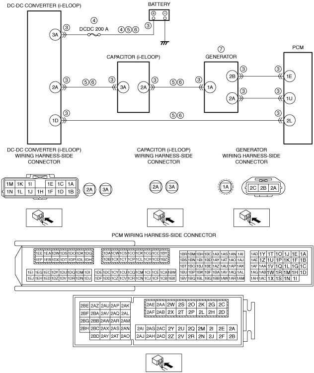
System Wiring Diagram (With i-ELOOP)
ac9wzw00004521
|
Function Explanation (DTC Detection Outline) (With i-ELOOP)
Repeatability Verification Procedure (With i-ELOOP)
PID Item/Simulation Item Used In Diagnosis (With i-ELOOP)
Function Inspection Using M-MDS (With i-ELOOP)
|
STEP |
INSPECTION |
RESULTS |
ACTION |
|---|---|---|---|
|
1
|
PURPOSE: RECORD VEHICLE STATUS AT TIME OF DTC DETECTION TO UTILIZE WITH REPEATABILITY VERIFICATION
• Record the snapshot data on the repair order.
|
—
|
Go to the next step.
|
|
2
|
PURPOSE: VERIFY RELATED SERVICE INFORMATION AVAILABILITY
• Verify related Service Information availability.
• Is any related Service Information available?
|
Yes
|
Perform repair or diagnosis according to the available Service Information.
• If the vehicle is not repaired, go to the next step.
|
|
No
|
Go to the next step.
|
||
|
3
|
PURPOSE: VERIFY IF GENERATOR VOLTAGE IS FALSELY RECOGNIZED BY DTC RELATED CURRENT SENSOR
• Switch the ignition off, then ON (engine off).
• Perform the Pending Trouble Code Access Procedure and DTC Reading Procedure.
• Is the PENDING CODE/DTC P058A:00 also present?
|
Yes
|
Repair or replace the malfunctioning part according to the applicable DTC troubleshooting.
Go to the next step.
|
|
No
|
Go to the next step.
|
||
|
4
|
PURPOSE: VERIFY DTC
• Retrieve the PCM DTCs using the M-MDS.
• Are any DTCs present?
|
Yes
|
Go to the applicable DTC inspection.
Go to the troubleshooting procedure to perform the procedure from Step 1.
|
|
No
|
Go to the troubleshooting procedure to perform the procedure from Step 1.
|
Troubleshooting Diagnostic Procedure (With i-ELOOP)
|
STEP |
INSPECTION |
RESULTS |
ACTION |
|---|---|---|---|
|
1
|
PURPOSE: DETERMINE THE MALFUNCTION CAUSE BY VERIFYING THE OUTPUT VOLTAGE OF GENERATOR TERMINAL 1A.
• Start the engine.
• Measure the voltage at the generator terminal 1A (wiring harness-side).
• Is the voltage approx. 0 V?
|
Yes
|
Perform the troubleshooting procedure for DTC P2503:00.
Go to the next step.
|
|
No
|
Go to the next step.
|
||
|
2
|
PURPOSE: VERIFY IF POOR CONNECTION OF EACH PART AFFECTS DIAGNOSTIC RESULTS
• Switch the ignition off.
• Remove the service plug.
• Inspect the connection condition (part installation condition, connector connection condition) for the following parts:
• Is the connection condition (part installation condition, connector connection condition) for each part normal?
|
Yes
|
Go to the next step.
|
|
No
|
Connect each part or the connector correctly, then go to Step 9.
|
||
|
3
|
PURPOSE: VERIFY IF CONNECTOR DAMAGE OF EACH PART AFFECTS DIAGNOSTIC RESULTS
• Disconnect the connector of the following parts.
• Inspect for poor connection (such as damaged/pulled-out pins, corrosion).
• Is there any malfunction?
|
Yes
|
Repair or replace the connector and/or terminals, then go to Step 9.
|
|
No
|
Go to the next step.
|
||
|
4
|
PURPOSE: INSPECT FUSE
• Remove the DCDC 200 A fuse.
• Inspect the DCDC 200 A fuse.
• Is there any malfunction?
|
Yes
|
If the fuse is blown:
• Refer to the wiring diagram and verify whether or not there is a common connector between DC-DC converter (i-ELOOP) terminal 3A and battery positive terminal.
If there is a common connector:
If there is no common connector:
If the fuse is damaged:
• Replace the fuse.
Go to Step 9.
|
|
No
|
Reinstall the DCDC 200 A fuse, then go to the next step.
|
||
|
5
|
PURPOSE: VERIFY IF SHORT TO GROUND IN EACH WIRING HARNESS AFFECTS DIAGNOSTIC RESULTS
• Verify that the battery, generator, PCM, capacitor (i-ELOOP), and DC-DC converter (i-ELOOP) connectors are disconnected.
• Inspect for continuity between the following terminals (wiring harness-side) and body ground:
• Is there continuity?
|
Yes
|
Refer to the wiring diagram and verify whether or not there is a common connector between the following terminals:
• DC-DC converter (i-ELOOP) terminal 3A—Battery positive terminal
• DC-DC converter (i-ELOOP) terminal 2A—Capacitor (i-ELOOP) terminal 3A
• DC-DC converter (i-ELOOP) terminal 1D—PCM terminal 2L
• Capacitor (i-ELOOP) terminal 2A—Generator terminal 1A
If there is a common connector:
• Determine the malfunctioning part by inspecting the common connector and the terminal for corrosion, damage, or pin disconnection, and the common wiring harness for a short to ground.
• Repair or replace the malfunctioning part.
If there is no common connector:
• Repair or replace the wiring harness which has a short to ground.
Go to Step 9.
|
|
No
|
Go to the next step.
|
||
|
6
|
PURPOSE: VERIFY IF OPEN CIRCUIT IN EACH WIRING HARNESS AFFECTS DIAGNOSTIC RESULTS
• Verify that the battery, generator, PCM, capacitor (i-ELOOP), and DC-DC converter (i-ELOOP) connectors are disconnected.
• Inspect for continuity between the following terminals (wiring harness-side):
• Is there continuity?
|
Yes
|
Go to the next step.
|
|
No
|
Refer to the wiring diagram and verify whether or not there is a common connector between the following terminals:
• DC-DC converter (i-ELOOP) terminal 3A—Battery positive terminal
• DC-DC converter (i-ELOOP) terminal 2A—Capacitor (i-ELOOP) terminal 3A
• DC-DC converter (i-ELOOP) terminal 1D—PCM terminal 2L
• Capacitor (i-ELOOP) terminal 2A—Generator terminal 1A
If there is a common connector:
• Determine the malfunctioning part by inspecting the common connector and the terminal for corrosion, damage, or pin disconnection, and the common wiring harness for an open circuit.
• Repair or replace the malfunctioning part.
If there is no common connector:
• Repair or replace the wiring harness which has an open circuit.
Go to Step 9.
|
||
|
7
|
PURPOSE: DETERMINE INTEGRITY OF GENERATOR
• Inspect the generator.
• Is there any malfunction?
|
Yes
|
Replace the generator, then go to the next step.
|
|
No
|
Go to the next step.
|
||
|
8
|
PURPOSE: VERIFY CONDITIONS OF BATTERY
• Inspect the battery.
(See BATTERY INSPECTION.)
|
—
|
Follow the inspection instructions, then go to the next step.
|
|
9
|
PURPOSE: VERIFICATION OF VEHICLE REPAIR COMPLETION
• Always reconnect all disconnected connectors.
• Reinstall the service plug.
• Clear the DTC from the PCM memory using the M-MDS.
• Implement the repeatability verification procedure.
• Perform the DTC Reading Procedure.
• Is the same DTC present?
|
Yes
|
Repeat the inspection from Step 1.
• If the malfunction recurs, replace the PCM.
Go to the next step.
|
|
No
|
Go to the next step.
|
||
|
10
|
PURPOSE: VERIFY IF THERE IS ANY OTHER MALFUNCTION
• Is any other DTC or pending code stored?
|
Yes
|
Go to the applicable DTC inspection.
|
|
No
|
DTC troubleshooting completed.
|