1. : Mazda SST number
2. : Global SST number
1: 49 UN30 3050
2: 303–050
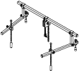
Engine lifting bracket
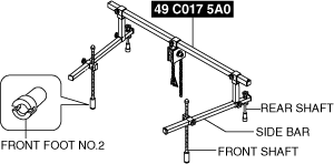
1: 49 C017 5A0
2: –
Engine support set
—
TIMING CHAIN REMOVAL/INSTALLATION [SKYACTIV-G 2.5T]
id0110q8801000
Special Service Tool (SST)
|
1. : Mazda SST number
2. : Global SST number
|
||||
|
1: 49 UN30 3050
2: 303–050
Engine lifting bracket
|
|
1: 49 C017 5A0
2: –
Engine support set
|
|
—
|
ac5wzw00003212
|
am6xuw00006584
|
1. Disconnect the negative battery terminal. (See NEGATIVE BATTERY TERMINAL DISCONNECTION/CONNECTION.)
2. Remove the plug hole plate. (See PLUG HOLE PLATE REMOVAL/INSTALLATION [SKYACTIV-G 2.5T].)
3. Remove the ignition coil/ion sensors. (See IGNITION COIL/ION SENSOR REMOVAL/INSTALLATION [SKYACTIV-G 2.5T].)
4. Remove the front under cover No.2. (See FRONT UNDER COVER No.2 REMOVAL/INSTALLATION.)
5. Remove the front splash shield (RH). (See FRONT SPLASH SHIELD REMOVAL/INSTALLATION.)
6. Remove the drive belt. (See DRIVE BELT REMOVAL/INSTALLATION [SKYACTIV-G 2.5T].)
7. Drain the engine oil. (See ENGINE OIL REPLACEMENT [SKYACTIV-G 2.5T].)
8. Remove the oil pan. (See OIL PAN REMOVAL/INSTALLATION [SKYACTIV-G 2.5T].)
9. Remove in the order indicated in the table.
10. Install in the reverse order of removal.
11. Refill with the specified type and amount of the engine oil. (See ENGINE OIL REPLACEMENT [SKYACTIV-G 2.5T].)
12. Start the engine and inspect the following:
Taiwan
ac9wzw00005708
|
Except Taiwan
ac9wzw00004735
|
|
1
|
Dipstick
|
|
2
|
Cylinder head cover
|
|
3
|
Oil shower pipe
|
|
4
|
Drive belt auto tensioner
|
|
5
|
Crankshaft pulley lock bolt
|
|
6
|
Crankshaft pulley
|
|
7
|
Front oil seal
|
|
8
|
No.3 engine mount
|
|
9
|
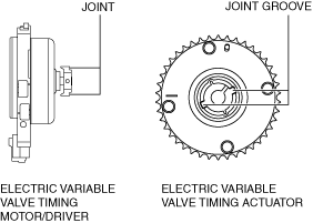
Electric variable valve timing motor/driver
|
|
10
|
Engine front cover
|
|
11
|
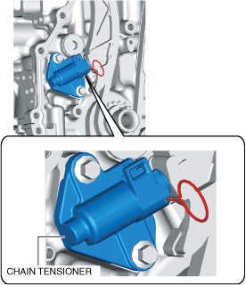
Chain tensioner
(See Timing Chain Removal Note.)
|
|
12
|
Tensioner arm
(See Timing Chain Removal Note.)
|
|
13
|
Chain guide (No.1)
(See Timing Chain Removal Note.)
|
|
14
|
Timing chain
(See Timing Chain Removal Note.)
|
|
15
|
Chain guide (No.2)
|
|
16
|
Crankshaft sprocket
|
|
17
|
Oil pump chain tensioner
(See Oil Pump Chain Removal Note.)
|
|
18
|
Balancer shaft sprocket
(See Oil Pump Chain Removal Note.)
|
|
19
|
Oil pump chain
(See Oil Pump Chain Removal Note.)
|
|
20
|
Oil pump driven sprocket
(See Oil Pump Chain Removal Note.)
|
|
21
|
Oil pump chain guide
|
|
22
|
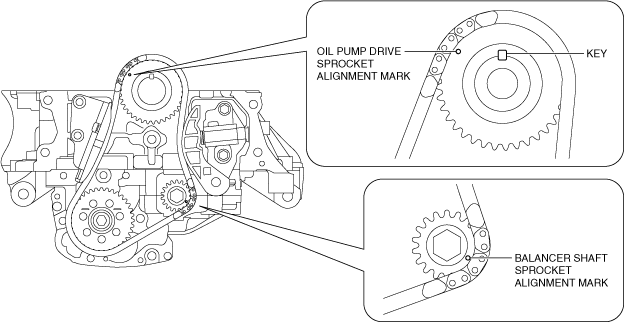
Oil pump drive sprocket
|
|
23
|
Key
|
Cylinder Head Cover Removal Note
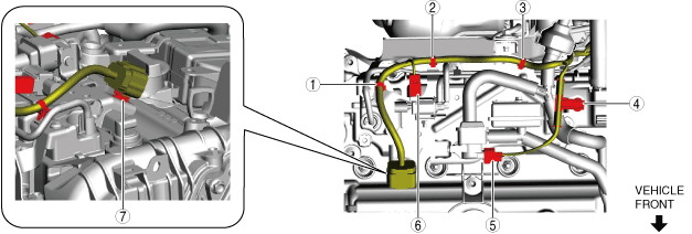
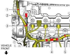
1. Disconnect the connectors and clips shown in the figure and set the wiring harness aside.
ac9uuw00006474
|
|
1
|
Wiring harness clip
|
|
2
|
Wiring harness clip
|
|
3
|
Wiring harness clip
|
|
4
|
Wiring harness clip
|
|
5
|
Purge solenoid valve connector
|
|
6
|
Solenoid valve connector
|
|
7
|
Wiring harness clip
|
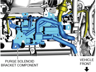
2. Disconnect the hoses shown in the figure and remove the purge solenoid bracket component.
ac9uuw00007426
|
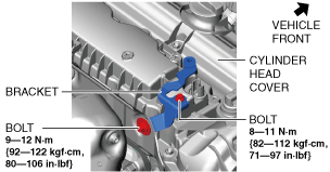
3. Remove the bolts shown in the figure and remove the bracket.
ac9wzw00003846
|
4. Remove the bolts and clips shown in the figure and remove the wiring harness bracket.
ac9uuw00006477
|
|
1
|
Wiring harness clip
|
|
2
|
Bolt
|
|
3
|
Wiring harness clip
|
|
4
|
Bolt
|
|
5
|
Wiring harness clip
|
|
6
|
Wiring harness bracket
|
5. Set the engine wiring harness aside using the following procedure:
Step 1
ac9uuw00006478
|
|
1
|
Wiring harness clip
|
|
2
|
OCV connector
|
|
3
|
Wiring harness clip
|
|
4
|
Wiring harness clip
|
|
5
|
Wiring harness clip
|
Step 2
ac9uuw00006479
|
|
1
|
Wiring harness clip
|
|
2
|
Fuel pressure sensor connector
|
|
3
|
High pressure fuel pump connector
|
|
4
|
Bolt
|
|
5
|
Camshaft position (CMP) sensor connector
|
|
6
|
Wiring harness clip
|
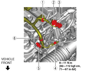
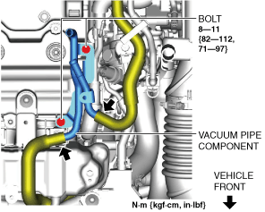
6. Disconnect the hoses shown in the figure and remove the vacuum pipe component.
ac9uuw00006480
|
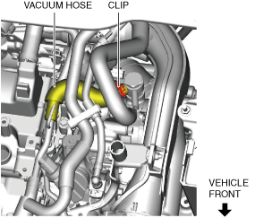
7. Disconnect the vacuum hose.
ac9uuw00006482
|
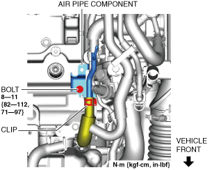
8. Disconnect the hose shown in the figure and set the air pipe component aside with the water hose still connected.
ac9uuw00006481
|
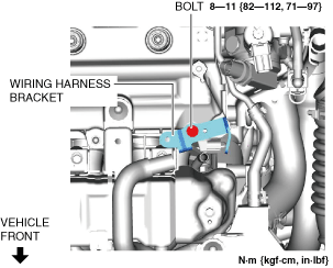
9. Remove the bolt shown in the figure and remove the wiring harness bracket.
ac9uuw00006483
|
10. Remove the air inlet pipe. (taiwan) (See INTAKE-AIR SYSTEM REMOVAL/INSTALLATION [SKYACTIV-G 2.5T].)
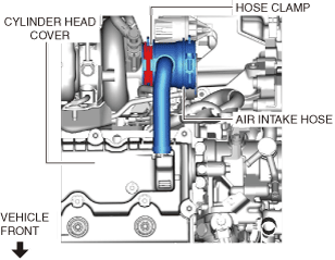
11. Disconnect the air intake hose shown in the figure. (taiwan)
ac9wzw00005709
|
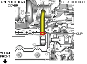
12. Disconnect the breather hose shown in the figure. (except taiwan)
ac9uuw00006485
|
13. Remove the cylinder head cover.
No.3 Engine Mount Removal Note
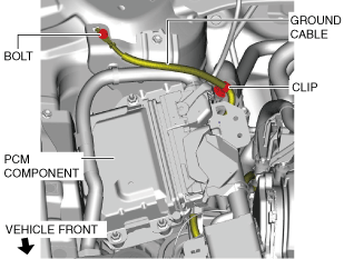
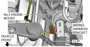
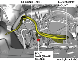
1. Remove the clip and bolt shown in the figure and set the ground cable aside.
ac9uuw00006486
|
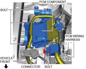
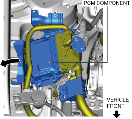
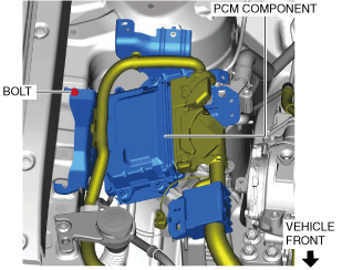
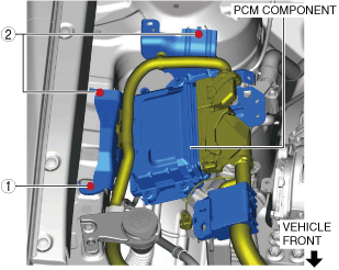
2. Set the PCM component aside using the following procedure:
ac9uuw00006487
|
ac9uuw00006488
|
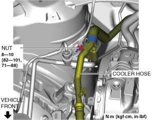
3. Remove the nut shown in the figure and set the cooler hose aside.
ac9uuw00006489
|
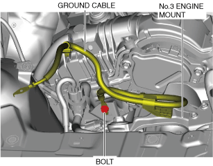
4. Disconnect the ground cable shown in the figure.
ac9uuw00006490
|
5. Disconnect the clip shown in the figure.
ac9uuw00006491
|
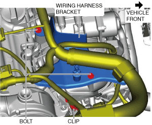
6. Remove the bolts and clip shown in the figure and set the wiring harness bracket aside.
ac9uuw00006492
|
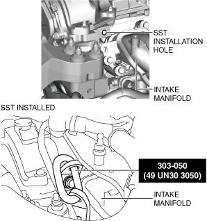
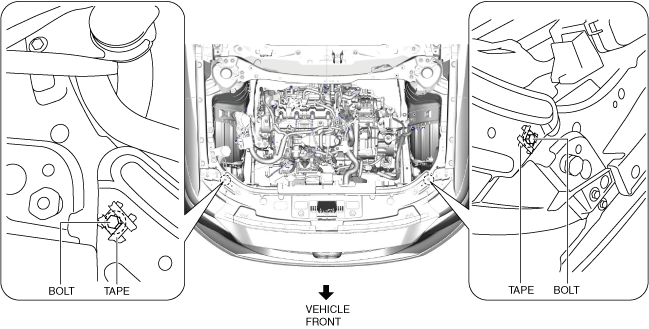
7. Install the SST using part number 99794 1025 or an M10 x 1.25, length 25 mm {0.98 in} bolt as shown in the figure.
ac9uuw00006493
|
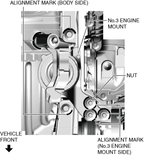
8. Place alignment marks on the locations shown in the figure so that they can be assembled to the same positions as before removal.
ac9uuw00006494
|
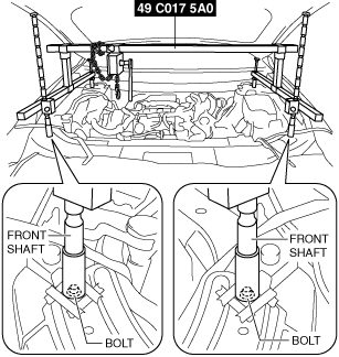
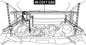
9. Install the SST using the following procedures.
am6zzw00010923
|
ac9uuw00006495
|
ac9uuw00006496
|
ac9uuw00006497
|
ac9uuw00006498
|
10. Remove the No.3 engine mount.
Engine Front Cover Removal Note
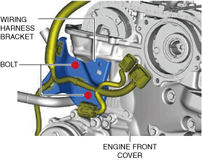
1. Remove the bolts shown in the figure and set the wiring harness bracket aside.
ac9uuw00006499
|
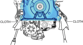
2. Remove the engine front cover installation bolts.
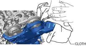
3. Using a screwdriver wrapped in a cloth, peel the sealant away a little at a time, and remove the engine front cover.
ac9uuw00006500
|
ac9uuw00006501
|
Timing Chain Removal Note
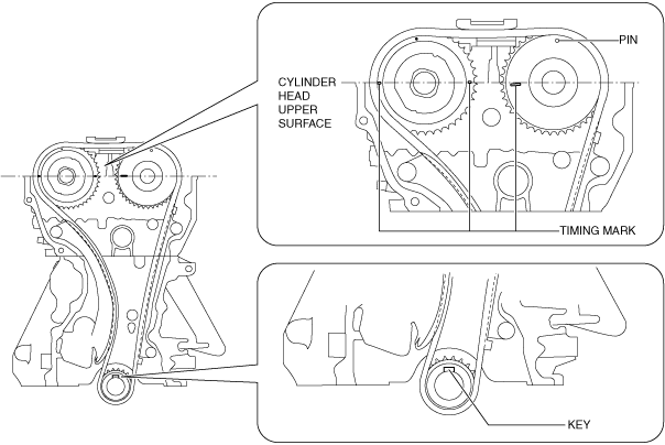
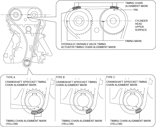
1. Rotate the crankshaft clockwise to align the timing marks and the key position as shown in the figure, and set cylinder No.1 at top dead center (TDC).
ac9wzw00005521
|
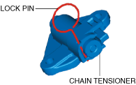
2. Verify the chain tensioner shape and identify the chain tensioner type.
ac4ccw00002689
|
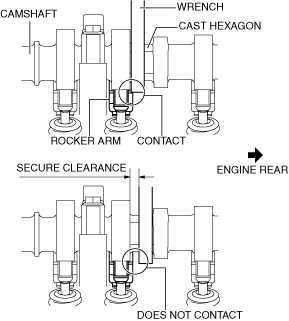
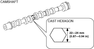
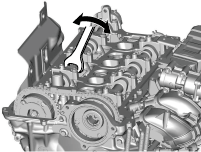
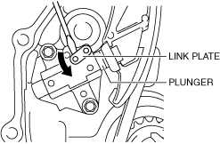
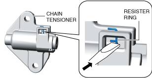
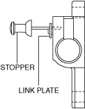
3. While moving the exhaust camshaft back and forth in the direction of the arrow using a wrench on the cast hexagon, press down the link plate of the timing chain tensioner using a precision screwdriver and release the plunger lock. (Chain tensioner type A)
ac9uuw00006503
|
ac5wzw00003230
|
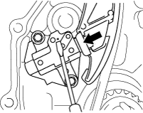
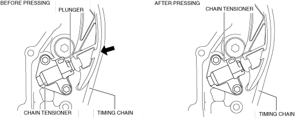
4. Push back the plunger slowly in the direction shown in the figure with the link plate still pushed down. (Chain tensioner type A)
ac5wzw00003231
|
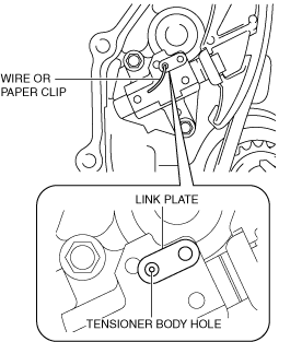
5. Remove the screwdriver from the link plate with the plunger still pushed down. (Chain tensioner type A)
6. Release the force slightly from the plunger, and move it back and forth 2—3 mm {0.08—0.11 in}. (Chain tensioner type A)
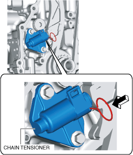
7. Insert a wire with an approx. diameter of 1.5 mm {0.059 in} or a paper clip where the link plate hole and the tensioner body hole overlap to secure the link plate and lock the plunger. (Chain tensioner type A)
ac5wzw00003232
|
8. Loosen the chain tensioner using the following procedure: (Chain tensioner type B)
amxzzw00003020
|
amxzzw00003021
|
amxuuw00004405
|
amxzzw00003022
|
9. Remove the chain tensioner, tensioner arm, and the chain guide (No.1).
10. Remove the timing chain.
Oil Pump Chain Removal Note
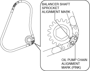
1. Verify that the balancer shaft sprocket alignment mark and key are aligned to the positions shown in the figure.
ac9uuw00006658
|
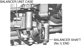
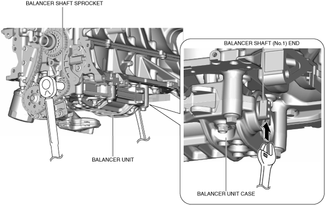
2. Slightly loosen the balancer shaft sprocket installation bolt using the following procedure:
ac9wzw00003847
|
ac9wzw00003848
|
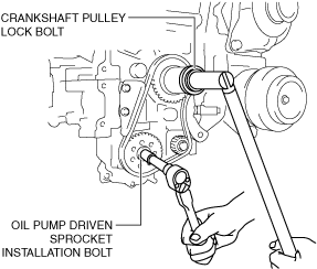
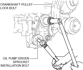
3. Slightly loosen the oil pump driven sprocket installation bolt using the following procedure:
ac9wzw00005096
|
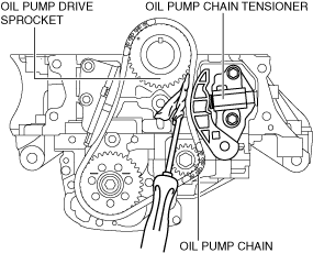
4. Set a cloth wrapped flathead screwdriver in the gap between the oil pump drive sprocket and the oil pump chain as shown in the figure.
ac9uuw00006507
|
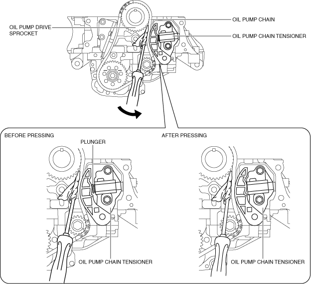
5. Move the screwdriver in the direction of the arrow and press the oil pump chain, and then press on the plunger of the oil pump chain tensioner.
ac9uuw00006508
|
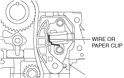
6. Insert a wire with an approx. diameter of 1.4 mm {0.055 in} or a paper clip into the body hole of the oil pump chain tensioner with the plunger pressed.
ac9uuw00006509
|
7. Remove the oil pump chain tensioner.
8. Remove the oil pump chain and balancer shaft sprocket as a single unit.
9. Remove the oil pump driven sprocket.
Oil Pump Chain Installation Note
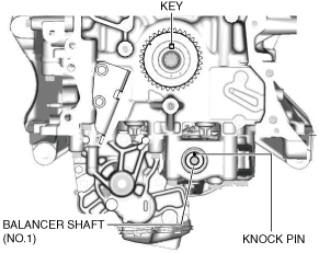
1. Verify that the key and knock pin are aligned to the positions shown in the figure.
ac9uuw00006510
|
2. Temporarily assemble the oil pump driven sprocket.
3. Temporarily tighten the oil pump driven sprocket installation bolt.
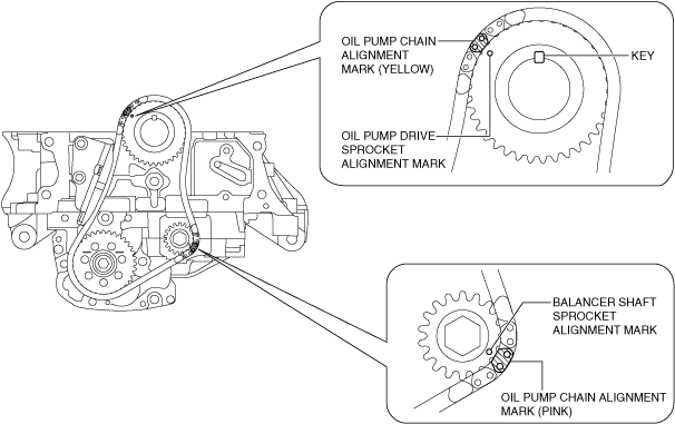
4. Align the oil pump chain alignment mark with the balancer shaft sprocket alignment mark.
ac9uuw00006511
|
5. Install the oil pump chain and balancer shaft sprocket as a single unit while aligning the alignment marks on each sprocket and oil pump chain as shown in the figure.
ac9wzw00005522
|
6. Temporarily tighten the balancer shaft sprocket installation bolt.
7. Install the oil pump chain tensioner.
8. Tighten the oil pump driven sprocket installation bolt using the following procedure:
ac5uuw00003191
|
9. Tighten the balancer shaft sprocket installation bolt using the following procedure:
ac9wzw00003847
|
ac9wzw00003848
|
10. Remove the wire or paper clip installed to the oil pump chain tensioner and apply tension to the oil pump chain.
Timing Chain Installation Note
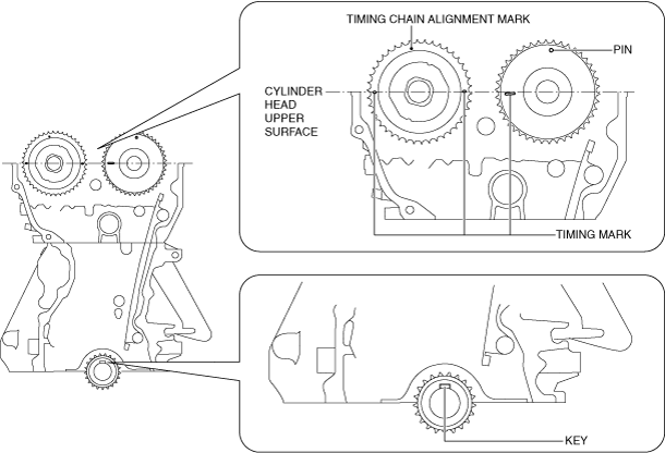
1. Verify that the timing marks and the key are aligned to the position shown in the figure.
ac9uuw00006514
|
2. Install the timing chain while aligning the marks on the timing chain as shown in the figure.
am6xuw00013286
|
3. Install the chain guide (No.1).
4. Install the tensioner arm.
5. Install the chain tensioner.
6. After installing the chain tensioner, remove the installed wire or paper clip, and then apply tension to the timing chain. (Chain tensioner type A)
ac5wzw00003237
|
7. After installing the timing chain tensioner, remove the installed rod, and then apply tension to the timing chain. (Chain tensioner type B)
ac9wzw00005710
|
8. Verify that there is no looseness in the timing chain, and re-verify that each sprocket is in the specified location.
9. Rotate the crankshaft clockwise two turns and inspect the valve timing.
ac9wzw00005521
|
Engine Front Cover Installation Note
ac9uuw00006516
|
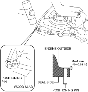
1. If the engine front cover is newly replaced, tap the positioning pins in the two locations to the seal surface side.
ac5wzw00003239
|
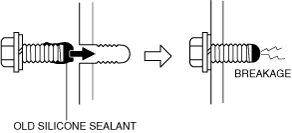
2. When reusing an engine front cover installation bolts, remove silicone sealant adhering to the bolts.
amxuuw00004413
|
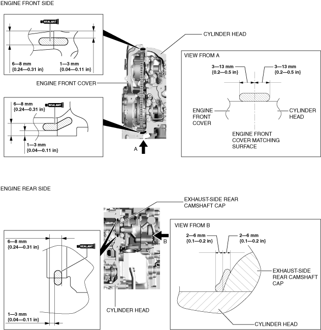
3. Completely clean and remove oil, dirt, silicone sealant or other foreign matter that may be adhering to the engine front cover, cylinder head, and cylinder block.
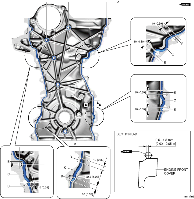
4. Apply silicone sealant (TB1217D or equivalent) to the engine front cover as shown in the figure.
ac9uuw00006517
|
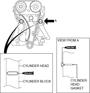
5. Apply silicone sealant to the areas shown in the figure.
ac9uuw00006659
|
6. Install the engine front cover to the engine.
ac9uuw00006519
|
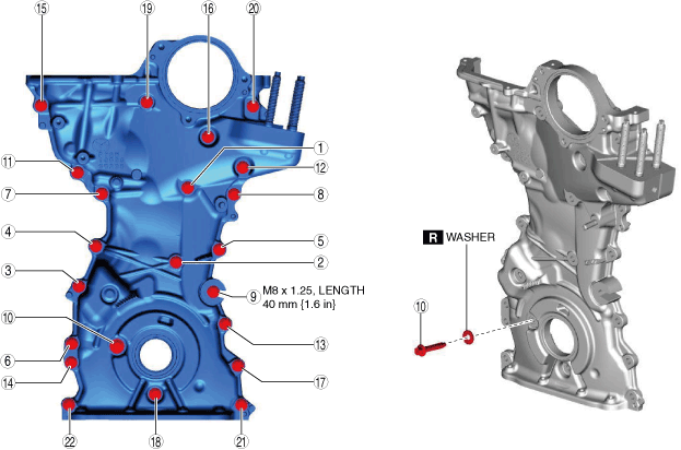
7. Prepare an appropriate M8 x 1.25 bolt (length 40 mm {1.6 in}).
8. Tighten the engine front cover installation bolts in the order shown in the figure.
ac9uuw00006520
|
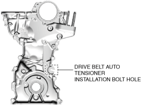
9. Remove the bolt installed to the drive belt auto tensioner installation bolt hole when installing the drive belt auto tensioner.
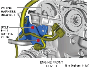
10. Install the wiring harness bracket shown in the figure.
ac9uuw00006521
|
Electric Variable Valve Timing Motor/Driver Installation Note
1. Install a new O-ring to the O-ring installation groove of the engine front cover.
am6xuw00006587
|
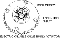
2. Install the electric variable valve timing motor/driver using the following procedures.
ac5wzw00003244
|
ac5wzw00003245
|
No.3 Engine Mount Installation Note
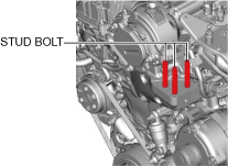
1. Tighten the engine front cover stud bolts.
ac9uuw00006522
|
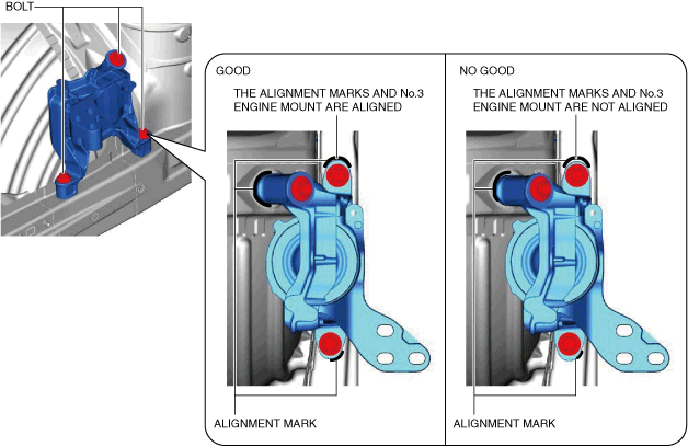
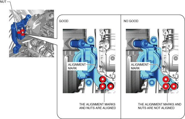
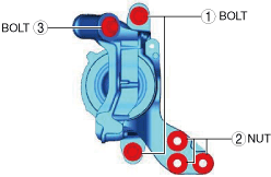
2. Temporarily tighten the No.3 engine mount installation bolts and nuts using the following procedure:
ac9uuw00006523
|
ac9uuw00006524
|
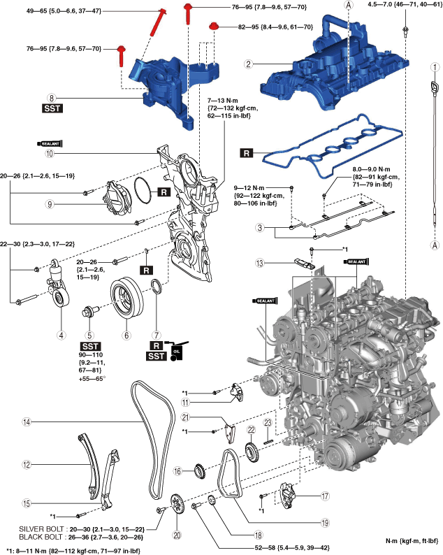
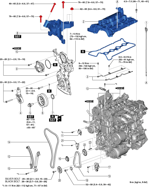
3. Tighten the No.3 engine mount installation bolts and nuts in the order as shown in the figure.
ac9uuw00006525
|
Tightening torque
|
Installation position |
Tightening torque |
|---|---|
|
1
|
76—95 N·m {7.8—9.6 kgf·m, 57—70 ft·lbf}
|
|
2
|
82—95 N·m {8.4—9.6 kgf·m, 61—70 ft·lbf}
|
|
3
|
49—65 N·m {5.0—6.6 kgf·m, 37—47 ft·lbf}
|
4. Remove the SST.
5. Return the wiring harness bracket to its original position.
6. Install the bolts and clip shown in the figure.
ac9uuw00006526
|
7. Connect the clip shown in the figure.
ac9uuw00006491
|
8. Install the ground cable shown in the figure.
ac9wzw00005564
|
9. Return the cooler hose that was set aside to its original position and tighten the nut.
ac9uuw00006527
|
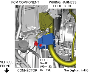
10. Install the PCM component using the following procedure:
ac9uuw00006528
|
ac9uuw00006529
|
ac9uuw00007427
|
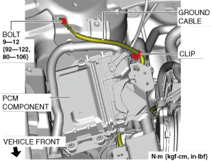
11. Install the ground cable shown in the figure.
ac9uuw00006531
|
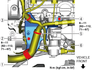
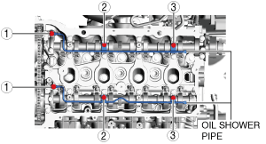
Oil Shower Pipe Installation Note
1. Install the oil shower pipe in the order shown in the figure.
ac9uuw00006532
|
Tightening torque
|
Installation position |
Tightening torque |
|---|---|
|
1
|
9—12 N·m {92—122 kgf·cm, 80—106 in·lbf}
|
|
2, 3
|
8.0—9.0 N·m {82—91 kgf·cm, 71—79 in·lbf}
|
Cylinder Head Cover Installation Note
1. Insert a new cylinder head cover gasket into the cylinder head cover groove.
2. Apply silicone sealant to the areas shown in the figure.
ac9uuw00006533
|
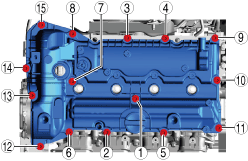
3. Tighten the cylinder cover bolts in the order shown in the figure.
ac9wzw00003849
|
4. Connect the breather hose shown in the figure. (except taiwan)
ac9uuw00006485
|
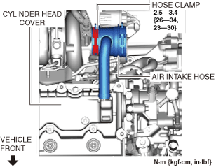
5. Install the air intake hose shown in the figure. (taiwan)
ac9wzw00005711
|
6. Install in the reverse order of removal.