|
am2zzw00008276
FRONT STABILIZER INSTALLATION
id021300803500
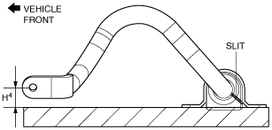
1. Install the front stabilizer bushing to the front stabilizer with the front stabilizer bushing slit part facing the vehicle rear.
am2zzw00008276
|
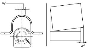
2. While maintaining the deviation in the positions of the front stabilizer bracket and the front stabilizer bushing within the range shown in the figure, install the front stabilizer bracket to the front stabilizer bushing. (See Front Stabilizer Bracket Installation Note.)
aatjjw00008415
|
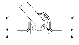
3. After installing the front stabilizer bracket, verify that the positions of the front stabilizer bracket and the front stabilizer bushing are within the range shown in the figure.
adejjw00012514
|
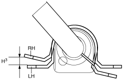
4. After installing the front stabilizer bracket, verify that the right and left-side positions of the front stabilizer bracket are within the range shown in the figure.
adejjw00012515
|
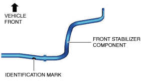
5. Place the front stabilizer component on a flat workbench, verify that the position of the front stabilizer end is within the range shown in the figure.
am2zzw00008277
|
6. Assemble the front stabilizer component so that the identification mark is on the right side of the vehicle.
ac9uuw00007953
|
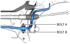
7. Temporarily tighten bolts A and B shown in the figure.
ac9uuw00007954
|
8. Tighten bolt B.
9. Tighten bolt A.
10. Tighten bolt B.
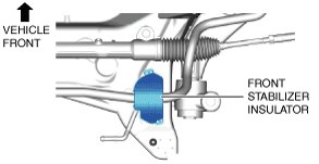
11. Install the front stabilizer insulator.
ac9uuw00007955
|
12. Install the front crossmember component. (See FRONT CROSSMEMBER REMOVAL/INSTALLATION.)
13. Install the splash shield. (See FRONT SPLASH SHIELD REMOVAL/INSTALLATION.)
14. Install the front under cover No.1. (See FRONT UNDER COVER No.1 REMOVAL/INSTALLATION.)
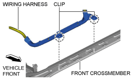
15. Assemble the wiring harness shown in the figure to the front crossmember. (Vehicle with i-ELOOP)
ac9wzw00003306
|
16. Install the front under cover No.2. (See FRONT UNDER COVER No.2 REMOVAL/INSTALLATION.)
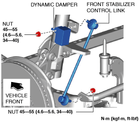
17. Install the front stabilizer control link.
ac9uuw00007956
|
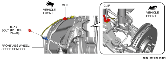
18. Assemble the front ABS wheel-speed sensor and the wiring harness clip as shown in the figure.
ac9uuw00007957
|
19. Connect the intermediate shaft to the steering gear and linkage. (See STEERING WHEEL AND COLUMN REMOVAL/INSTALLATION.)
20. Install the joint cover. (See STEERING WHEEL AND COLUMN REMOVAL/INSTALLATION.)
21. Install the wheels and tires. (See WHEEL AND TIRE REMOVAL/INSTALLATION.)
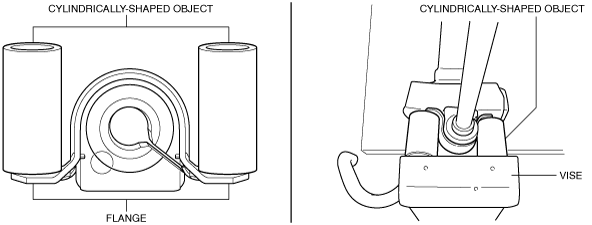
Front Stabilizer Bracket Installation Note
1. If the front stabilizer bracket cannot be installed by hand, install it using a vise.
am2zzw00008281
|