49 T028 3A0
Ball joint puller set
FRONT CROSSMEMBER REMOVAL/INSTALLATION
id021300801000
Special Service Tool (SST)
|
49 T028 3A0
Ball joint puller set
|
|
1. Remove the wheels and tires. (See WHEEL AND TIRE REMOVAL/INSTALLATION.)
2. Remove the joint cover. (See STEERING WHEEL AND COLUMN REMOVAL/INSTALLATION.)
3. Disconnect the intermediate shaft from the steering gear and linkage. (See STEERING WHEEL AND COLUMN REMOVAL/INSTALLATION.)
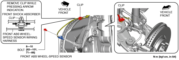
4. Disconnect the front ABS wheel-speed sensor wiring harness installed to the steering knuckle and set it aside. (See FRONT ABS WHEEL-SPEED SENSOR REMOVAL/INSTALLATION.)
ac9uuw00007932
|
5. Remove the front under cover No.2. (See FRONT UNDER COVER No.2 REMOVAL/INSTALLATION.)
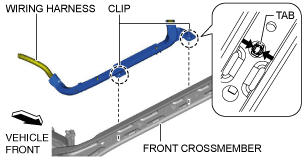
6. Disconnect the wiring harness from the front crossmember. (Vehicle with i-ELOOP)
ac9wzw00003303
|
7. Remove the front under cover No.1. (See FRONT UNDER COVER No.1 REMOVAL/INSTALLATION.)
8. Remove the front splash shield. (See FRONT SPLASH SHIELD REMOVAL/INSTALLATION.)
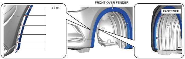
9. Remove the fasteners and clips shown in the figure and partially peel back the front over fender.
ac9uuw00007933
|
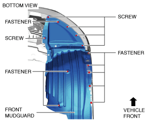
10. Remove the screws and the fasteners shown in the figure and set the front mudguard aside.
ac9uuw00007934
|
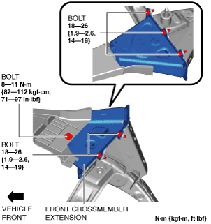
11. Remove the front crossmember extension.
ac9uuw00007935
|
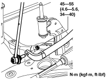
12. Disconnect the front stabilizer control link (front stabilizer side).
ac5uuw00000128
|
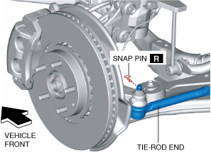
13. Remove the snap pin from the tie-rod end.
ac9wzw00005534
|
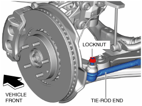
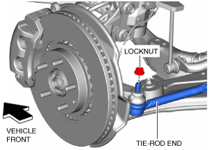
14. Loosen the locknut of the tie-rod end.
ac9uuw00006200
|
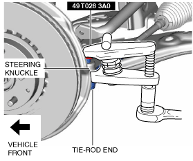
15. Using the SST, disconnect the steering knuckle and tie-rod end.
ac9uuw00006201
|
16. Remove the locknut from the tie-rod end.
ac9uuw00006202
|
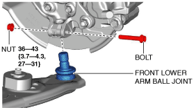
17. Disconnect the front lower arm ball joint. (See Front Lower Arm Ball Joint Installation Note.)
ac9uuw00007937
|
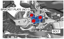
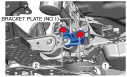
18. Remove the bracket plate (No.1). (2WD)
ac9uuw00007938
|
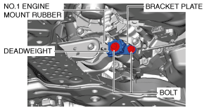
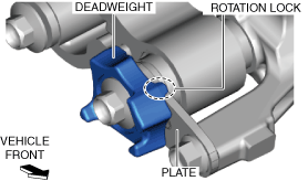
19. Remove the deadweight and bracket plate. (4WD)
ac9uuw00007939
|
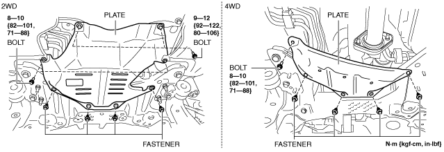
20. Remove the plate.
ac9wzw00004116
|
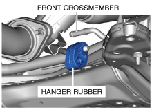
21. Disconnect the hanger rubber from the front crossmember and set it aside.
ac9uuw00007942
|
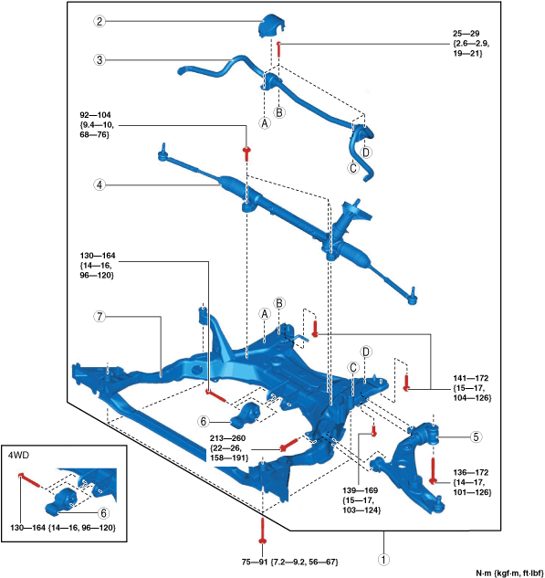
22. Remove in the order indicated in the table.
23. Install in the reverse order of removal. (See Suspension Links Installation Note.)
24. When replacing the front crossmember, inspect the wheel alignment and adjust it if necessary. (See FRONT WHEEL ALIGNMENT.)
ac9wzw00003304
|
|
1
|
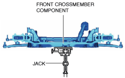
Front crossmember component
|
|
2
|
Front stabilizer insulator
(See FRONT STABILIZER REMOVAL.)
|
|
3
|
Front stabilizer
(See FRONT STABILIZER REMOVAL.)
|
|
4
|
Steering gear and linkage
|
|
5
|
Front lower arm
|
|
6
|
No.1 engine mount rubber
|
|
7
|
Front crossmember
|
Front Crossmember Component Removal Note
1. Support the front crossmember component using a jack.
ac9uuw00007944
|
2. Remove the front crossmember installation bolts.
3. Remove the front crossmember, front stabilizer, front lower arm, and steering gear and linkage as a single unit.
Suspension Links Installation Note
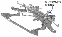
1. When installing the joint sections with rubber bushings, perform the following procedures.
No.1 Engine Mount Rubber and Front Crossmember Component Installation Note
2WD
ac9uuw00007945
|
1. Temporarily install the bracket plate (No.1) and No.1 engine mount rubber.
ac9uuw00007938
|
2. Tighten the bracket plate (No.1) installation bolts in the order shown in the figure.
ac9uuw00007946
|
|
No. |
Tightening torque |
|---|---|
|
1
|
131—153 N·m {14—15 kgf·m, 97—112 ft·lbf}
|
|
2
|
131—153 N·m {14—15 kgf·m, 97—112 ft·lbf}
|
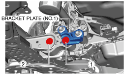
3. Tighten the No.1 engine mount rubber installation bolts in the order shown in the figure.
ac9uuw00007947
|
|
No. |
Tightening torque |
|---|---|
|
1
|
130—151 N·m {14—15 kgf·m, 96—111 ft·lbf}
|
|
2
|
130—164 N·m {14—16 kgf·m, 96—120 ft·lbf}
|
4WD
ac9uuw00007945
|
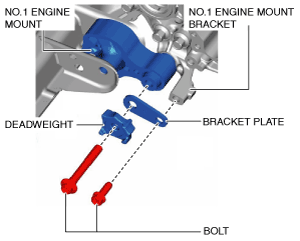
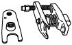
1. Temporarily install the No. 1 engine mount rubber, bracket plate, and deadweight.
ac8wzw00002540
|
ac9uuw00007948
|
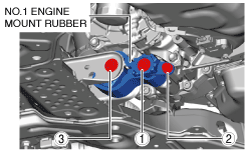
2. Tighten the installation bolts for the No. 1 engine mount rubber, bracket plate, and deadweight in the order shown in the figure.
ac9uuw00007949
|
|
No. |
Tightening torque |
|---|---|
|
1
|
140—163 N·m {15—16 kgf·m, 104—120 ft·lbf}
|
|
2
|
55—69 N·m {5.7—7.0 kgf·m, 41—50 ft·lbf}
|
|
3
|
130—164 N·m {14—16 kgf·m, 96—120 ft·lbf}
|
Front Lower Arm Ball Joint Installation Note
1. Insert the bolt from the front of the vehicle and tighten the nut to the specified torque.