 |
ac9wzw00004486
ELECTRIC PARKING BRAKE AUTOMATIC RELEASE FUNCTION DURING ACCELERATION DOES NOT OPERATE [ELECTRIC PARKING BRAKE]
id040328250500
Description
Possible cause
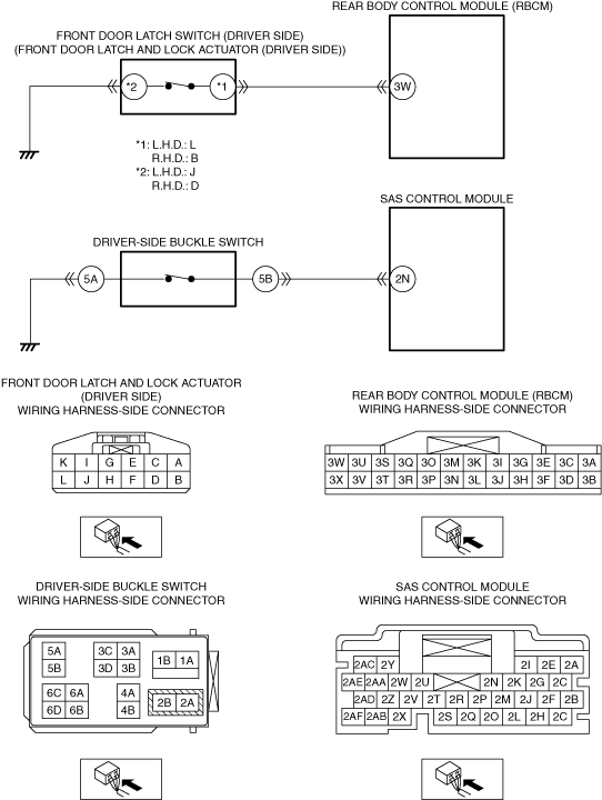
System wiring diagram
ac9wzw00004486
|
Diagnostic Procedure
|
Step |
Inspection |
Action |
|
|---|---|---|---|
|
1
|
VERIFY ALL SYSTEM DTCs
• Switch the ignition OFF.
• Switch the ignition ON (engine off or on) and wait for 10 s or more.
• Perform a CMDTC self-test using the M-MDS.
• Are any DTCs displayed?
|
Yes
|
Repair or replace the malfunctioning part according to the applicable DTC troubleshooting.
|
|
No
|
Go to the next step.
|
||
|
2
|
VERIFY IF THE ELECTRIC PARKING BRAKE WARNING LIGHT IS TURNED ON
• Verify if the electric parking brake warning light is turned on.
• Is the electric parking brake warning light turned on?
|
Yes
|
Perform an inspection referring to “ELECTRIC PARKING BRAKE WARNING LIGHT TURNS ON”.
|
|
No
|
Go to the next step.
|
||
|
3
|
DETERMINE MALFUNCTIONING LOCATION BY PERFORMING PID/DATA MONITOR INSPECTION
• Using the M-MDS, display the following PIDs for the rear body control module (RBCM).
• Using the M-MDS, display the following PIDs for the SAS control module.
• Does the PID monitoring value switch correctly in conjunction with the opening/closing of the front door (driver’s side) or with the driver's seat belt fastened?
|
Yes
|
Replace the electric parking brake control module.
|
|
No
|
Not in conjunction with front door (driver’s side) open/close
• Go to the next step.
Not in conjunction with driver's seat belt fastened
• Go to Step 8.
|
||
|
4
|
INSPECT FRONT DOOR LATCH AND LOCK ACTUATOR (DRIVER’S SIDE) CONNECTOR CONDITION
• Switch the ignition OFF.
• Disconnect the negative battery terminal.
• Disconnect the front door latch and lock actuator (driver’s side) connector.
• Inspect the connector engagement and connection condition and inspect the terminals for damage, deformation, corrosion, or disconnection.
• Is the connector normal?
|
Yes
|
Go to the next step.
|
|
No
|
Repair or replace the connector.
|
||
|
5
|
INSPECT FRONT DOOR LATCH SWITCH (DRIVER’S SIDE)
• Inspect the front door latch switch (driver’s side).
• Is the front door latch switch (driver’s side) normal?
|
Yes
|
Go to the next step.
|
|
No
|
Replace the front door latch and lock actuator (driver’s side).
|
||
|
6
|
INSPECT REAR BODY CONTROL MODULE (RBCM) CONNECTOR CONDITION
• Disconnect the rear body control module (RBCM) connector.
• Inspect the connector engagement and connection condition and inspect the terminals for damage, deformation, corrosion, or disconnection.
• Is the connector normal?
|
Yes
|
Go to the next step.
|
|
No
|
Repair or replace the connector.
|
||
|
7
|
INSPECT FRONT DOOR LATCH SWITCH (DRIVER’S SIDE) CIRCUIT FOR SHORT TO GROUND
• Verify that the front door latch and lock actuator (driver's side) and rear body control module (RBCM) connectors are disconnected.
• Inspect for continuity between the following terminals (wiring harness-side) and body ground:
• Is there continuity?
|
Yes
|
Refer to the wiring diagram and verify whether or not there is a common connector between the following terminals:
• L.H.D.
• R.H.D.
If there is a common connector:
• Determine the malfunctioning part by inspecting the common connector and the terminal for corrosion, damage, or pin disconnection, and the common wiring harness for a short to ground.
• Repair or replace the malfunctioning part.
If there is no common connector:
• Repair or replace the wiring harness which has a short to ground.
|
|
No
|
Replace the rear body control module (RBCM).
|
||
|
8
|
INSPECT DRIVER-SIDE BUCKLE SWITCH CONNECTOR CONDITION
• Switch the ignition off.
• Disconnect the negative battery terminal and wait for 1 min or more.
• Disconnect the driver-side buckle switch connector.
• Inspect the connector engagement and connection condition and inspect the terminals for damage, deformation, corrosion, or disconnection.
• Is the connector normal?
|
Yes
|
Go to the next step.
|
|
No
|
Repair or replace the connector.
|
||
|
9
|
INSPECT DRIVER-SIDE BUCKLE SWITCH
• Inspect the driver-side buckle switch.
(See BUCKLE SWITCH INSPECTION.)
• Is the driver-side buckle switch normal?
|
Yes
|
Go to the next step.
|
|
No
|
Replace the driver-side front buckle.
|
||
|
10
|
INSPECT SAS CONTROL MODULE CONNECTOR CONDITION
• Disconnect the SAS control module connector.
• Inspect the connector engagement and connection condition and inspect the terminals for damage, deformation, corrosion, or disconnection.
• Is the connector normal?
|
Yes
|
Go to the next step.
|
|
No
|
Repair or replace the connector.
|
||
|
11
|
INSPECT DRIVER-SIDE BUCKLE SWITCH CIRCUIT FOR SHORT TO GROUND
• Verify that the driver-side buckle switch and SAS control module connectors are disconnected.
• Inspect for continuity between driver-side buckle switch terminal 5B (wiring harness-side) and body ground.
• Is there continuity?
|
Yes
|
Refer to the wiring diagram and verify whether or not there is a common connector between driver-side buckle switch terminal 5B and SAS control module terminal 2N.
If there is a common connector:
• Determine the malfunctioning part by inspecting the common connector and the terminal for corrosion, damage, or pin disconnection, and the common wiring harness for a short to ground.
• Repair or replace the malfunctioning part.
If there is no common connector:
• Repair or replace the wiring harness which has a short to ground.
|
|
No
|
Replace the SAS control module.
|
||