REAR BODY CONTROL MODULE (RBCM) REMOVAL/INSTALLATION
id094000002000
-
Caution
-
• If configuration is not performed when the rear body control module (RBCM) is replaced with a new one, the vehicle specification information is not stored in the rear body control module (RBCM) and the system will not operate normally.
• When performing configuration, it is necessary to read the vehicle specification information from the rear body control module (RBCM) before replacing it. Connect the M-MDS to the vehicle and perform vehicle identification before removing the rear body control module (RBCM). The vehicle specification information is temporarily stored in the M-MDS.
-
Note
-
• The rear body control module (RBCM) prior to replacement stores the vehicle specification information.
• A new rear body control module (RBCM) does not store any vehicle specification information.
• If the vehicle specification information from the rear body control module (RBCM) prior to replacement cannot be read, perform the configuration using As-Built data.
1. When replacing the rear body control module (RBCM), perform the configuration. (See REAR BODY CONTROL MODULE (RBCM) CONFIGURATION (USING READ/WRITE FUNCTION).)
2. Operate the door lock actuator using the following procedure and deplete the energy stored in the backup power supply.
-
Note
-
• If the energy stored in the backup power supply has already been depleted, the door lock actuator does not operate. As this does not indicate an improper procedure, continue to perform the procedure as indicated.
- (1) Remove the D.LOCK 25A fuse.
-
- (2) Close the front door (driver's side)
-
- (3) Repeat the lock/unlock operation of the door lock switch (driver's side) until all the door lock knobs do not move. (With door lock switch)
-
- (4) Repeat the lock/unlock operation of the door lock knob (driver's side) until the door lock knobs other than the driver's seat do not move. (Without door lock switch)
-
3. Disconnect the negative battery terminal. (See NEGATIVE BATTERY TERMINAL DISCONNECTION/CONNECTION.)
4. Remove the following parts:
- (1) Trunk covering (See TRUNK COVERING REMOVAL/INSTALLATION.)
-
- (2) Trunk board (See TRUNK BOARD REMOVAL/INSTALLATION.)
-
- (3) Trunk side pocket (LH) (See TRUNK SIDE POCKET REMOVAL/INSTALLATION.)
-
- (4) Trunk end trim (See TRUNK END TRIM REMOVAL/INSTALLATION.)
-
- (5) Rear scuff plate (LH) (See REAR SCUFF PLATE REMOVAL/INSTALLATION.)
-
- (6) Third-row seat cushion (See THIRD-ROW SEAT CUSHION REMOVAL/INSTALLATION.)
-
- (7) Third-row seat back component (See THIRD-ROW SEAT BACK COMPONENT REMOVAL/INSTALLATION.)
-
- (8) Trunk side trim (LH) (See TRUNK SIDE TRIM REMOVAL/INSTALLATION.)
-
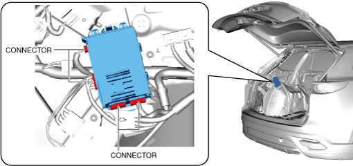
5. Disconnect the connector shown in the figure. (with backup power supply)
6. Remove the bolts. (with backup power supply)
7. Remove the backup power supply component. (with backup power supply)
8. Disconnect the connectors shown in the figure.
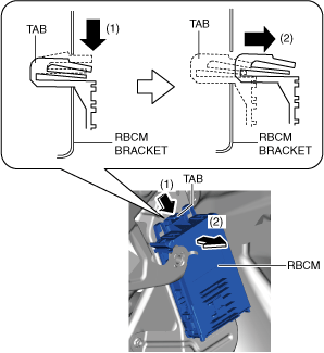
9. While pressing the rear body control module (RBCM) tab in the direction of arrow (1) shown in the figure, pull it in the direction of arrow (2) to detach the tab from the rear body control module (RBCM) bracket.
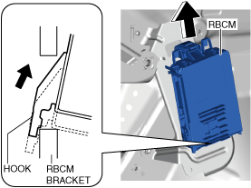
10. Pull the rear body control module (RBCM) up in the direction of the arrow to detach the hook from the rear body control module (RBCM) bracket.
11. Remove the rear body control module (RBCM).
12. Install in the reverse order of removal.
-
Note
-