 |
ac9uuw00006749
FUEL GAUGE SENDER UNIT INSPECTION [4WD]
id0922000121b3
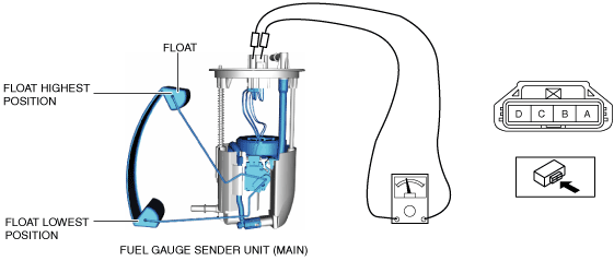
Fuel gauge sender unit (main)
1. Complete the “BEFORE SERVICE PRECAUTION”. (See BEFORE SERVICE PRECAUTION [SKYACTIV-G 2.5T].)
2. If the fuel gauge level indicates 3/4 or more, refer to the “FUEL DRAINING PROCEDURE” and drain the fuel. (See FUEL DRAINING PROCEDURE [SKYACTIV-G 2.5T].)
3. Disconnect the negative battery terminal. (See NEGATIVE BATTERY TERMINAL DISCONNECTION/CONNECTION.)
4. Remove the second-row seat (LH). (See SECOND-ROW SEAT REMOVAL/INSTALLATION.)
5. Remove the fuel pump unit. (See FUEL PUMP UNIT REMOVAL/INSTALLATION [SKYACTIV-G 2.5T].)
6. Verify that the resistance between fuel pump unit terminals C and D is as indicated in the table.
ac9uuw00006749
|
|
Condition of float |
Resistance (ohm) |
|---|---|
|
Float is at top position
|
18.5—21.5
|
|
Float is at bottom position
|
197—203
|
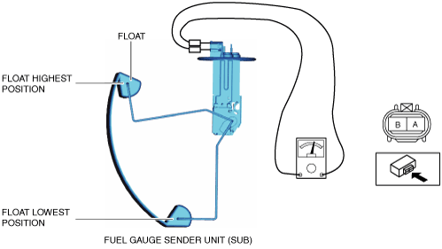
Fuel gauge sender unit (sub)
1. Complete the “BEFORE SERVICE PRECAUTION”. (See BEFORE SERVICE PRECAUTION [SKYACTIV-G 2.5T].)
2. Refer to the “FUEL DRAINING PROCEDURE” and drain the fuel. (See FUEL DRAINING PROCEDURE [SKYACTIV-G 2.5T].)
3. Disconnect the negative battery terminal. (See NEGATIVE BATTERY TERMINAL DISCONNECTION/CONNECTION.)
4. Remove the second-row seat (RH). (See SECOND-ROW SEAT REMOVAL/INSTALLATION.)
5. Remove the fuel gauge sender unit (sub). (See FUEL GAUGE SENDER UNIT REMOVAL/INSTALLATION [4WD].)
6. Verify that the resistance between fuel gauge sender unit (sub) terminals A and B is as indicated in the table.
ac9uuw00006750
|
|
Condition of float |
Resistance (ohm) |
|---|---|
|
Float is at top position
|
18.5—21.5
|
|
Float is at bottom position
|
197—203
|