DTC C0023:62/C0040:64 [DSC HU/CM]


id040262906400

Caution
•  Vehicle specifications differ depending on the vehicle identification number (VIN).
?  Type A VIN:
JM0 TC2WLA*# 100001—299999
JM0 TC4WLA*# 100001—299999
JMZ TB5WYA*# 100001—599999
JMZ TB6WYA*# 100001—599999
JMZ TBEWYA*# 100001—599999
JMZ TBFWYA*# 100001—599999
JM7 TC2WLA*# 100001—299999
JM7 TC4WLA*# 100001—299999
JM5 TCAWY**# 100001—299999
JM6 TC2WLA*# 100001—299999
JM6 TC4WLA*# 100001—299999
?  Type B VIN:
JM0 TC2WLA*# 300001—399999
JM0 TC4WLA*# 300001—399999
JMZ TB5WYA*# 600001—
JMZ TB6WYA*# 600001—
JMZ TBEWYA*# 600001—699999
JMZ TBFWYA*# 600001—699999
JM7 TC2WLA*# 300001—399999
JM7 TC4WLA*# 300001—399999
JM5 TCAWY**# 300001—399999
JM6 TC2WLA*# 300001—399999
JM6 TC4WLA*# 300001—399999
?  Type C VIN:
JM0 TC2WLA*# 400001—
JM0 TC4WLA*# 400001—
JMZ TBEWYA*# 700001—
JMZ TBFWYA*# 700001—
JM7 TC2WLA*# 400001—
JM7 TC4WLA*# 400001—
JM5 TCAWY**# 400001—
JM6 TC2WLA*# 400001—
JM6 TC4WLA*# 400001—

DTC

C0023:62

Brake switch

C0040:64

DETECTION CONDITION
•  C0023:62
?  Brake light signal cannot be detected even though brake light signal is requested.
?  Error detected in signal from rear body control module via CAN communication.
•  C0040:64
?  Accelerator pedal is depressed and brake switch on condition continues for 30 to 60 s while vehicle is driven at 10.8 km/h {6.71 mph} or more.
?  A brake switch ON signal is not input when the brake fluid pressure sensor signal reaches the specified value.
FAIL-SAFE FUNCTION
•  Refer to “Fail-safe function table”. (See DTC TABLE [DSC HU/CM].)
POSSIBLE CAUSE
Without smart brake support (SBS) and applied VIN type A or B
•  Brake switch malfunction
•  Open or short circuit in wiring harness between brake switch terminal D and brake light relay terminal B
•  Brake light relay malfunction
•  Open or short circuit in wiring harness between brake light relay terminal D and DSC HU/CM terminal O
•  Rear body control module malfunction
•  Poor connection at each connector
•  DSC HU/CM malfunction
With smart brake support (SBS) or applied VIN type C
•  Brake switch malfunction
•  Open or short circuit in wiring harness between brake switch terminal D and brake light unit terminal I
•  Open or short circuit in wiring harness between brake light unit terminal H and DSC HU/CM terminal O
•  Brake light unit malfunction
•  Poor connection at each connector
•  DSC HU/CM malfunction

Diagnostic Procedure


Without smart brake support (SBS) and applied VIN type A or B

Step

Inspection

Action

1
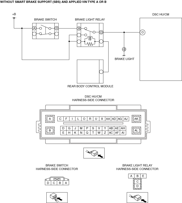
INSPECT BRAKE LIGHT RELAY VOLTAGE
•  Remove the brake light relay.
•  Measure the voltage between brake light relay terminal B (wiring harness-side) and body ground.
•  Is the voltage within followings?
?  Brake pedal depressed: B+
?  Brake pedal released: 1.0 V or less
Yes
Go to step 4.
No
•  If it is B+ under any condition, then go to the next step.
•  If it is 1.0 V or less under any condition, then go to Step 3.
2
INSPECT BRAKE SWITCH
•  Inspect brake switch.
•  Is the brake switch normal?
Yes
Refer to the wiring diagram and verify whether or not there is a common connector between brake switch terminal D and brake light relay terminal B.
If there is a common connector:
•  Determine the malfunctioning part by inspecting the common connector and the terminal for corrosion, damage, or pin disconnection, and the common wiring harness for a short to power circuit.
•  Repair or replace the malfunctioning part.
If there is no common connector:
•  Repair or replace the wiring harness which has a short to power circuit.
Go to step 7.
No
Replace the brake switch, then go to step 7.
3
INSPECT BRAKE SWITCH
•  Inspect brake switch.
•  Is the brake switch normal?
Yes
Refer to the wiring diagram and verify whether or not there is a common connector between brake switch terminal D and brake light relay terminal B.
If there is a common connector:
•  Determine the malfunctioning part by inspecting the common connector and the terminal for corrosion, damage, or pin disconnection, and the common wiring harness for an open or short to ground circuit.
•  Repair or replace the malfunctioning part.
If there is no common connector:
•  Repair or replace the wiring harness which has an open or short to ground circuit.
Go to step 7.
No
Replace the brake switch, then go to step 7.
4
INSPECT BRAKE LIGHT RELAY
•  Remove the brake light relay.
•  Inspect brake light relay.
•  Is the brake light relay normal?
Yes
Go to the next step.
No
Replace the brake light relay, then go to step 7.
5
INSPECT WIRING HARNESS BETWEEN BRAKE LIGHT RELAY AND DSC HU/CM FOR OPEN OR SHORT CIRCUIT
•  Disconnect the DSC HU/CM connector.
•  Measure the voltage between DSC HU/CM terminal O (wiring harness-side) and body ground.
•  Is the voltage within followings?
?  Brake pedal depressed: B+
?  Brake pedal released: 1.0 V or less
Yes
Go to the next step.
No
•  If it is B+ under any condition, refer to the wiring diagram and verify whether or not there is a common connector between brake light relay terminal D and DSC HU/CM terminal O.
If there is a common connector:
•  Determine the malfunctioning part by inspecting the common connector and the terminal for corrosion, damage, or pin disconnection, and the common wiring harness for a short to power circuit.
•  Repair or replace the malfunctioning part.
If there is no common connector:
•  Repair or replace the wiring harness which has a short to power circuit.
•  If it is 1.0 V or less under any condition, refer to the wiring diagram and verify whether or not there is a common connector between brake light relay terminal D and DSC HU/CM terminal O.
If there is a common connector:
•  Determine the malfunctioning part by inspecting the common connector and the terminal for corrosion, damage, or pin disconnection, and the common wiring harness for an open or short to ground circuit.
•  Repair or replace the malfunctioning part.
If there is no common connector:
•  Repair or replace the wiring harness which has an open or short to ground circuit.
•  Go to step 7.
6
VERIFY REAR BODY CONTROL MODULE (RBCM) DTC
•  Using the M-MDS, perform the Rear Body Control Module (RBCM) DTC inspection.
•  Are any DTCs present?
Yes
Go to the applicable DTC inspection.
DTC troubleshooting completed, then go to the next step.
No
Go to the next step.
7
VERIFY DTC TROUBLESHOOTING COMPLETED
•  Using the M-MDS, clear the DTC from the DSC HU/CM.
•  Using the M-MDS, perform the DSC HU/CM DTC inspection.
•  Is the same DTC present?
Yes
If the malfunction recurs, replace the DSC HU/CM, then go to the next step.
No
Go to the next step.
8
VERIFY NO DTC IS PRESENT
•  Are any DTCs present?
Yes
Go to the applicable DTC inspection.
No
DTC troubleshooting completed.


With smart brake support (SBS) or applied VIN type C

Step

Inspection

Action

1
INSPECT BRAKE LIGHT UNIT VOLTAGE
•  Disconnect the brake light unit connector.
•  Measure the voltage between brake light unit terminal I (wiring harness-side) and body ground.
•  Is the voltage within followings?
?  Brake pedal depressed: B+
?  Brake pedal released: 1.0 V or less
Yes
Go to step 4.
No
•  If it is B+ under any condition, then go to the next step.
•  If it is 1.0 V or less under any condition, then go to Step 3.
2
INSPECT BRAKE SWITCH
•  Inspect brake switch.
•  Is the brake switch normal?
Yes
Refer to the wiring diagram and verify whether or not there is a common connector between brake switch terminal D and brake light unit terminal I.
If there is a common connector:
•  Determine the malfunctioning part by inspecting the common connector and the terminal for corrosion, damage, or pin disconnection, and the common wiring harness for a short to power circuit.
•  Repair or replace the malfunctioning part.
If there is no common connector:
•  Repair or replace the wiring harness which has a short to power circuit.
Go to step 6.
No
Replace the brake switch, then go to step 6.
3
INSPECT BRAKE SWITCH
•  Inspect brake switch.
•  Is the brake switch normal?
Yes
Refer to the wiring diagram and verify whether or not there is a common connector between brake switch terminal D and brake light unit terminal I.
If there is a common connector:
•  Determine the malfunctioning part by inspecting the common connector and the terminal for corrosion, damage, or pin disconnection, and the common wiring harness for an open or short to ground circuit.
•  Repair or replace the malfunctioning part.
If there is no common connector:
•  Repair or replace the wiring harness which has an open or short to ground circuit.
Go to step 6.
No
Replace the brake switch, then go to step 6.
4
INSPECT WIRING HARNESS BETWEEN BRAKE LIGHT UNIT AND DSC HU/CM FOR OPEN OR SHORT CIRCUIT
•  Disconnect the DSC HU/CM connector.
•  Measure the voltage between DSC HU/CM terminal O (wiring harness-side) and body ground.
•  Is the voltage within followings?
?  Brake pedal depressed: B+
?  Brake pedal released: 1.0 V or less
Yes
Go to the next step.
No
•  If it is B+ under any condition, refer to the wiring diagram and verify whether or not there is a common connector between brake light unit terminal H and DSC HU/CM terminal O.
If there is a common connector:
•  Determine the malfunctioning part by inspecting the common connector and the terminal for corrosion, damage, or pin disconnection, and the common wiring harness for a short to power circuit.
•  Repair or replace the malfunctioning part.
If there is no common connector:
•  Repair or replace the wiring harness which has a short to power circuit.
•  If it is 1.0 V or less under any condition, refer to the wiring diagram and verify whether or not there is a common connector between brake light unit terminal H and DSC HU/CM terminal O.
If there is a common connector:
•  Determine the malfunctioning part by inspecting the common connector and the terminal for corrosion, damage, or pin disconnection, and the common wiring harness for an open or short to ground circuit.
•  Repair or replace the malfunctioning part.
If there is no common connector:
•  Repair or replace the wiring harness which has an open or short to ground circuit.
•  Go to step 6.
5
INSPECT BRAKE LIGHT UNIT
•  Inspect the brake light unit.
•  Is the brake light unit normal?
Yes
Go to the next step.
No
Replace the brake light unit, then go to the next step.
6
VERIFY DTC TROUBLESHOOTING COMPLETED
•  Using the M-MDS, clear the DTC from the DSC HU/CM.
•  Using the M-MDS, perform the DSC HU/CM DTC inspection.
•  Is the same DTC present?
Yes
If the malfunction recurs, replace the DSC HU/CM, then go to the next step.
No
Go to the next step.
7
VERIFY NO DTC IS PRESENT
•  Are any DTCs present?
Yes
Go to the applicable DTC inspection.
No
DTC troubleshooting completed.