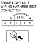
Terminal voltage list (reference)
ac9uuw00007123
|
|
Terminal |
Signal |
Connection |
Test condition |
Voltage (V) |
Inspection item(s) |
|
|---|---|---|---|---|---|---|
|
A
|
Ground
|
Body ground
|
Under any condition
|
1.0 or less
|
Body ground
|
|
|
B
|
—
|
—
|
—
|
—
|
—
|
|
|
D
|
Brake light illumination request signal
|
Rear body control module (RBCM)
|
Connect the M-MDS and turn on the “STOP_LMP_CS” using the rear body control module (RBCM) simulation function
|
1.0 or less
|
• Rear body control module (RBCM)
• Related wiring harness
|
|
|
Connect the M-MDS and turn off the “STOP_LMP_CS” using the rear body control module (RBCM) simulation function
|
B+
|
|||||
|
F
|
Power supply
|
STOP 10 A fuse
|
Under any condition
|
B+
|
• STOP 10 A fuse
• Battery
|
|
|
G
|
High-mount brake light signal
|
High-mount brake light
|
Brake pedal depressed
|
B+
|
High-mount brake light
|
|
|
Brake pedal not depressed
|
1.0 or less
|
|||||
|
H
|
Brake light illumination status signal
|
DSC HU/CM
|
Brake pedal depressed
|
B+
|
DSC HU/CM
|
|
|
Brake pedal not depressed
|
1.0 or less
|
|||||
|
I
|
Brake switch (No.1 signal) signal
|
Brake switch (No.1 signal)
|
Brake pedal depressed
|
B+
|
Brake switch (No.1 signal)
|
|
|
Brake pedal not depressed
|
1.0 or less
|
|||||
|
J
|
Brake light signal
|
• Brake light
• Rear body control module (RBCM)
|
Brake pedal depressed
|
B+
|
• Brake light
• Rear body control module (RBCM)
|
|
|
Brake pedal not depressed
|
1.0 or less
|
|||||