STEP
INSPECTION
ACTION
1
INSPECT BRAKE FLUID AMOUNT AND VERIFY THAT PARKING BRAKE IS RELEASED
• Inspect the brake fluid amount and verify that the parking brake is released.
• Is the brake fluid amount normal?
• Is the electric parking brake released?
Yes
Go to the next step.
No
Add the brake fluid or release the electric parking brake switch.
If the brake fluid amount is less than specification:
• Inspect and repair the brake line for leakage.
2
CONFIRM DSC HU/CM DTC
• Retrieve the DSC HU/CM DTC using the M-MDS.
(See DTC INSPECTION [DSC HU/CM].)
• Are any DTCs present?
Yes
Go to the applicable DTC inspection.
(See DTC TABLE [DSC HU/CM].)
No
Go to the next step.
3
CONFIRM INSTRUMENT CLUSTER OPERATION RECORD
• Retrieve the warning system operation history using the M-MDS.
• Is the brake system warning light illumination history recorded?
Yes
If the Brake Warning Lamp is recorded:
• Go to the next step.
If the Brake Warning Lamp (Brake fluid low) is recorded:
• Go to Step 5.
If the Brake Warning Lamp (Parking Brake ON over 20 km/h or 12.4 mile/h) is recorded:
• Go to Step 7.
No
Go to Step 9.
4
VERIFY IF MALFUNCTION IS IN INSTRUMENT CLUSTER OR ELSEWHERE
• Perform Warning/Indicator Light Illumination Inspection.
• Does the brake system warning light illumination?.
Yes
Go to Step 9.
No
Replace the instrument cluster.
5
VERIFY IF MALFUNCTION IS IN BRAKE FLUID LEVEL SENSOR OR ELSEWHERE
• Inspect the brake fluid level sensor.
• Is the brake fluid level sensor normal?
Yes
Go to the next step.
No
Replace the master cylinder assembly.
*6
INSPECT FOR SHORT TO GROUND IN WIRING HARNESS BETWEEN FRONT BODY CONTROL MODULE (FBCM) AND BRAKE FLUID LEVEL SENSOR
• Inspect for short to ground in the following circuit:
-
? Between brake fluid level sensor and front body control module (FBCM) terminal 2Q
• Is a short to ground detected?
Yes
Repair or replace the wiring harness for a possible short to ground.
No
Retrieve the front body control module (FBCM) DTC using the M-MDS.
If the DTC remains:
• Go to the applicable DTC inspection.
If the DTC does not remain:
• Replace the front body control module (FBCM).
7
INSPECT WHETHER MALFUNCTION IS IN ELECTRIC PARKING BRAKE SWITCH OR ELSEWHERE
• Inspect the following parts for continuity:
-
? Electric parking brake switch
• Is the continuity condition normal?
Yes
Go to the next step.
No
Replace the electric parking brake switch.
*8
INSPECT FOR SHORT TO GROUND IN WIRING HARNESS BETWEEN INSTRUMENT CLUSTER AND ELECTRIC PARKING BRAKE SWITCH
• Inspect for short to ground in the following circuit:
-
? Between electric parking brake switch terminal J and instrument cluster terminal 1L
• Is the short to ground detected?
Yes
Repair or replace the wiring harness for a possible short to ground.
No
Retrieve the instrument cluster DTC using the M-MDS.
If the DTC remains:
• Go to the applicable DTC inspection.
If the DTC does not remain:
• Replace the instrument cluster.
9
VERIFY IF MALFUNCTION IS IN DSC HU/CM CONNECTOR FOR POOR CONNECTION OR ELSEWHERE
• Switch the ignition ON.
• Does the ABS warning light, brake warning light, TCS/DSC indicator light, and TCS OFF indicator light (without Off-road traction assist)/Off-road traction assist indicator light (with Off-road traction assist) turn off after 2 to 4 s?
Yes
Inspect the DSC HU/CM connector or terminal. (poor connection intermittently)
• If there is a malfunction, repair or replace any malfunctioning parts according to the inspection result.
No
Go to the next step.
10
INSPECT BATTERY VOLTAGE
• Switch the ignition OFF.
• Inspect the battery voltage.
(See BATTERY INSPECTION.)
• Is the battery voltage normal?
Yes
Go to the next step.
No
Recharge the battery and inspect the charging system.
(See BATTERY INSPECTION.)
• If there is a malfunction, repair or replace any malfunctioning parts according to the inspection result.
11
VERIFY IF MALFUNCTION IS IN CHARGING SYSTEM OR ELSEWHERE
• Measure the battery voltage with electrical loads (such as A/C, headlight) applied while idling.
• Is the battery voltage normal?
Yes
Go to the next step.
No
Inspect the charging system (drive belt, generator).
• If there is a malfunction, repair or replace any malfunctioning parts according to the inspection result.
12
INSPECT CONNECTION OF DSC HU/CM CONNECTOR
• Inspect connection of the DSC HU/CM connector.
• Is the DSC HU/CM connector connected securely?
Yes
Go to the next step.
No
Connect the DSC HU/CM connector securely, then go to the next step.
13
INSPECT CONNECTION OF CONNECTOR TERMINAL
• Is there a poor connection in the DSC HU/CM, instrument cluster, or related-connector terminal?
Yes
Repair the poor connection location of the terminal.
-
Note
-
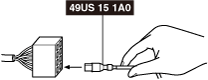
• Tool used (Reference): PROBE KIT (49US-15-1A0)
 amxzzw00004444
No
Go to the next step.
14
VERIFY IF MALFUNCTION IS IN WIRING HARNESS (BETWEEN DSC HU/CM POWER SUPPLY AND DSC HU/CM FOR CONTINUITY) OR ELSEWHERE
• Switch the ignition ON.
• Measure the voltage at the DSC HU/CM terminal I (wiring harness-side).
• Is the voltage approx. 12 V?
Yes
Go to the next step.
No
Refer to the wiring diagram and verify whether or not there is a common connector between DSC HU/CM terminal I (wiring harness-side) and ignition switch.
If there is a common connector:
• Determine the malfunctioning part by inspecting the common connector and the terminal for corrosion, damage, or pin disconnection, and the common wiring harness for an open circuit.
• Repair or replace the malfunctioning part.
If there is no common connector:
• Repair or replace the wiring harness which has an open circuit.
15
VERIFY IF MALFUNCTION IS IN WIRING HARNESS (BETWEEN DSC HU/CM AND GROUND FOR CONTINUITY) OR ELSEWHERE
• Switch the ignition OFF.
• Disconnect the DSC HU/CM connector.
• Inspect for continuity between DSC HU/CM terminal AK (wiring harness-side) and body ground.
• Is there continuity?
Yes
Replace the DSC HU/CM. (open circuit in the DSC HU/CM)
No
Repair or replace the wiring harness for a possible open circuit and poor contact at the ground point, then go to the next step.
16
CONFIRM INSTRUMENT CLUSTER DTC
• Retrieve the instrument cluster DTC using the M-MDS.
• Are any DTCs present?
Yes
Go to the applicable DTC inspection.
No
Replace the instrument cluster.