Note
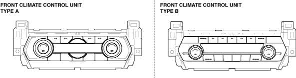
• There are two types of front climate control unit, type A and type B.
ac9wzw00005447
|
DTC B10FB:71 [CLIMATE CONTROL UNIT (FULL-AUTO AIR CONDITIONER)]
id0702k2816400
ac9wzw00005447
|
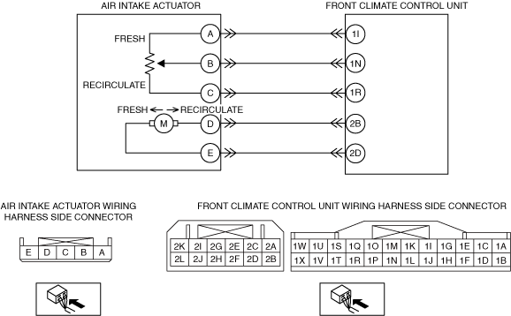
Front Climate Control Unit Type A
|
System malfunction location |
• Air intake actuator motor lock
|
|---|---|
|
Detection condition
|
• Air intake actuator motor lock
|
|
Fail-safe function
|
Malfunction determined when ignition switched ON
• Air intake actuator drive signal is stopped right when the malfunction is determined.
Malfunction already exists when ignition switched ON
• Fifteen seconds after the ignition is switched ON, the air intake actuator drive signal is output normally again. Afterwards, motor output is stopped during malfunction determination.
|
|
Possible cause
|
• Connector or terminal malfunction
• Air intake actuator malfunction
• Blower unit (air intake link) malfunction
• Open circuit in wiring harness between front climate control unit and air intake actuator
• Short circuit to power supply or body ground in wiring harness between front climate control unit and air intake actuator
• Front climate control unit malfunction
|
 |
|
Diagnostic procedure
|
STEP |
INSPECTION |
ACTION |
|
|---|---|---|---|
|
1
|
VERIFY RELATED DTC
• Switch the ignition off.
• Perform the DTC inspection for the climate control unit using the M-MDS.
• Is DTC B11F0:12, B11F0:13 or U200D:11 also present?
|
Yes
|
Repair or replace the malfunctioning part according to the applicable DTC troubleshooting.
|
|
No
|
Go to the next step.
|
||
|
2
|
INSPECT AIR INTAKE ACTUATOR CONNECTOR
• Switch the ignition off.
• Disconnect the negative battery terminal.
• Disconnect the air intake actuator connector.
(See AIR INTAKE ACTUATOR REMOVAL.)
• Inspect the connector and terminals (corrosion, damage, pin disconnection).
• Are the connector and terminals normal?
|
Yes
|
Go to the next step.
|
|
No
|
Repair/replace the connector or terminal.
After repair procedure, go to Step 9.
|
||
|
3
|
INSPECT AIR INTAKE ACTUATOR
• Inspect the air intake actuator.
• Is it normal?
|
Yes
|
Go to the next step.
|
|
No
|
Replace the air intake actuator.
Go to Step 9.
|
||
|
4
|
INSPECT AIR INTAKE LINK OPERATION
• Operate the air intake link manually.
• Does the air intake link operate smoothly?
|
Yes
|
Go to the next step.
|
|
No
|
Replace the air intake link.
Go to Step 9.
|
||
|
5
|
INSPECT AIR INTAKE ACTUATOR CIRCUIT FOR OPEN CIRCUIT
• Disconnect the front climate control unit connector.
• Inspect for continuity between the following terminals (wiring harness-side):
• Is there continuity?
|
Yes
|
Go to the next step.
|
|
No
|
Refer to the wiring diagram and verify whether or not there is a common connector between front climate control unit terminal and air intake actuator terminal.
If there is a common connector:
• Determine the malfunctioning part by inspecting the common connector and the terminal for corrosion, damage, or pin disconnection, and the common wiring harness for an open circuit.
• Repair or replace the malfunctioning part.
If there is no common connector:
• Repair or replace the wiring harness which has an open circuit.
Go to Step 9.
|
||
|
6
|
INSPECT AIR INTAKE ACTUATOR CIRCUIT FOR SHORT TO GROUND
• Inspect for continuity between the following terminals (wiring harness-side) and body ground:
• Is there continuity?
|
Yes
|
Refer to the wiring diagram and verify whether or not there is a common connector between front climate control unit terminal and air intake actuator terminal.
If there is a common connector:
• Determine the malfunctioning part by inspecting the common connector and the terminal for corrosion, damage, or pin disconnection, and the common wiring harness for a short to ground.
• Repair or replace the malfunctioning part.
If there is no common connector:
• Repair or replace the wiring harness which has a short to ground.
Go to Step 9.
|
|
No
|
Go to the next step.
|
||
|
7
|
INSPECT AIR INTAKE ACTUATOR CIRCUIT FOR SHORT TO POWER SUPPLY
• Connect the negative battery terminal.
• Switch the ignition on (engine off or on).
• Measure the voltage at the following terminals (wiring harness-side):
• Is the voltage 0 V?
|
Yes
|
Go to the next step.
|
|
No
|
Refer to the wiring diagram and verify whether or not there is a common connector between front climate control unit terminal and air intake actuator terminal.
If there is a common connector:
• Determine the malfunctioning part by inspecting the common connector and the terminal for corrosion, damage, or pin disconnection, and the common wiring harness for a short to power supply.
• Repair or replace the malfunctioning part.
If there is no common connector:
• Repair or replace the wiring harness which has a short to power supply.
Go to Step 9.
|
||
|
8
|
VERIFY FRONT CLIMATE CONTROL UNIT CONNECTOR CONDITION
• Switch the ignition off.
• Disconnect the negative battery terminal.
• Inspect the connector and terminals (corrosion, damage, pin disconnection).
• Are the connector and terminals normal?
|
Yes
|
Go to the next step.
|
|
No
|
Repair/replace the connector or terminal.
After repair procedure, go to the next step.
|
||
|
9
|
VERIFY THAT SAME DTC IS NOT OUTPUT AGAIN
• Reconnect the disconnected connectors.
• Connect the negative battery terminal.
• Clear the DTC from the climate control unit memory using the M-MDS.
• Perform the DTC inspection for the climate control unit using the M-MDS.
• Is the same DTC displayed?
|
Yes
|
Repeat the inspection from Step 1.
• If the malfunction recurs, replace the front climate control unit.
Go to the next step.
|
|
No
|
Go to the next step.
|
||
|
10
|
VERIFY THAT NO OTHER DTCs ARE PRESENT
• Verify other DTCs displayed.
• Are any other DTCs displayed?
|
Yes
|
Repair or replace the malfunctioning part according to the applicable DTC troubleshooting.
|
|
No
|
DTC troubleshooting completed.
|
||
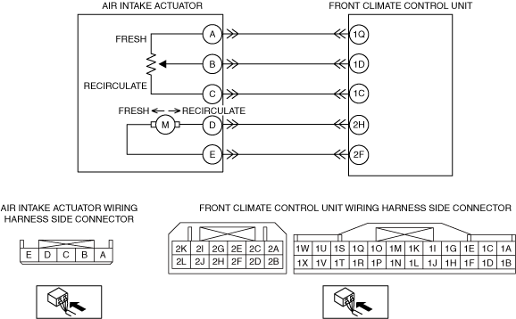
Front Climate Control Unit Type B
|
System malfunction location |
• Air intake actuator motor lock
|
|---|---|
|
Detection condition
|
• Air intake actuator motor lock
|
|
Fail-safe function
|
Malfunction determined when ignition switched ON
• Air intake actuator drive signal is stopped right when the malfunction is determined.
Malfunction already exists when ignition switched ON
• Fifteen seconds after the ignition is switched ON, the air intake actuator drive signal is output normally again. Afterwards, motor output is stopped during malfunction determination.
|
|
Possible cause
|
• Connector or terminal malfunction
• Air intake actuator malfunction
• Blower unit (air intake link) malfunction
• Open circuit in wiring harness between front climate control unit and air intake actuator
• Short circuit to power supply or body ground in wiring harness between front climate control unit and air intake actuator
• Front climate control unit malfunction
|
 |
|
Diagnostic procedure
|
STEP |
INSPECTION |
ACTION |
|
|---|---|---|---|
|
1
|
VERIFY RELATED DTC
• Switch the ignition off.
• Perform the DTC inspection for the climate control unit using the M-MDS.
• Is DTC B11F0:12, B11F0:13 or U200D:11 also present?
|
Yes
|
Repair or replace the malfunctioning part according to the applicable DTC troubleshooting.
|
|
No
|
Go to the next step.
|
||
|
2
|
INSPECT AIR INTAKE ACTUATOR CONNECTOR
• Switch the ignition off.
• Disconnect the negative battery terminal.
• Disconnect the air intake actuator connector.
(See AIR INTAKE ACTUATOR REMOVAL.)
• Inspect the connector and terminals (corrosion, damage, pin disconnection).
• Are the connector and terminals normal?
|
Yes
|
Go to the next step.
|
|
No
|
Repair/replace the connector or terminal.
After repair procedure, go to Step 9.
|
||
|
3
|
INSPECT AIR INTAKE ACTUATOR
• Inspect the air intake actuator.
• Is it normal?
|
Yes
|
Go to the next step.
|
|
No
|
Replace the air intake actuator.
Go to Step 9.
|
||
|
4
|
INSPECT AIR INTAKE LINK OPERATION
• Operate the air intake link manually.
• Does the air intake link operate smoothly?
|
Yes
|
Go to the next step.
|
|
No
|
Replace the air intake link.
Go to Step 9.
|
||
|
5
|
INSPECT AIR INTAKE ACTUATOR CIRCUIT FOR OPEN CIRCUIT
• Disconnect the front climate control unit connector.
• Inspect for continuity between the following terminals (wiring harness-side):
• Is there continuity?
|
Yes
|
Go to the next step.
|
|
No
|
Refer to the wiring diagram and verify whether or not there is a common connector between front climate control unit terminal and air intake actuator terminal.
If there is a common connector:
• Determine the malfunctioning part by inspecting the common connector and the terminal for corrosion, damage, or pin disconnection, and the common wiring harness for an open circuit.
• Repair or replace the malfunctioning part.
If there is no common connector:
• Repair or replace the wiring harness which has an open circuit.
Go to Step 9.
|
||
|
6
|
INSPECT AIR INTAKE ACTUATOR CIRCUIT FOR SHORT TO GROUND
• Inspect for continuity between the following terminals (wiring harness-side) and body ground:
• Is there continuity?
|
Yes
|
Refer to the wiring diagram and verify whether or not there is a common connector between front climate control unit terminal and air intake actuator terminal.
If there is a common connector:
• Determine the malfunctioning part by inspecting the common connector and the terminal for corrosion, damage, or pin disconnection, and the common wiring harness for a short to ground.
• Repair or replace the malfunctioning part.
If there is no common connector:
• Repair or replace the wiring harness which has a short to ground.
Go to Step 9.
|
|
No
|
Go to the next step.
|
||
|
7
|
INSPECT AIR INTAKE ACTUATOR CIRCUIT FOR SHORT TO POWER SUPPLY
• Connect the negative battery terminal.
• Switch the ignition on (engine off or on).
• Measure the voltage at the following terminals (wiring harness-side):
• Is the voltage 0 V?
|
Yes
|
Go to the next step.
|
|
No
|
Refer to the wiring diagram and verify whether or not there is a common connector between front climate control unit terminal and air intake actuator terminal.
If there is a common connector:
• Determine the malfunctioning part by inspecting the common connector and the terminal for corrosion, damage, or pin disconnection, and the common wiring harness for a short to power supply.
• Repair or replace the malfunctioning part.
If there is no common connector:
• Repair or replace the wiring harness which has a short to power supply.
Go to Step 9.
|
||
|
8
|
VERIFY FRONT CLIMATE CONTROL UNIT CONNECTOR CONDITION
• Switch the ignition off.
• Disconnect the negative battery terminal.
• Inspect the connector and terminals (corrosion, damage, pin disconnection).
• Are the connector and terminals normal?
|
Yes
|
Go to the next step.
|
|
No
|
Repair/replace the connector or terminal.
After repair procedure, go to the next step.
|
||
|
9
|
VERIFY THAT SAME DTC IS NOT OUTPUT AGAIN
• Reconnect the disconnected connectors.
• Connect the negative battery terminal.
• Clear the DTC from the climate control unit memory using the M-MDS.
• Perform the DTC inspection for the climate control unit using the M-MDS.
• Is the same DTC displayed?
|
Yes
|
Repeat the inspection from Step 1.
• If the malfunction recurs, replace the front climate control unit.
Go to the next step.
|
|
No
|
Go to the next step.
|
||
|
10
|
VERIFY THAT NO OTHER DTCs ARE PRESENT
• Verify other DTCs displayed.
• Are any other DTCs displayed?
|
Yes
|
Repair or replace the malfunctioning part according to the applicable DTC troubleshooting.
|
|
No
|
DTC troubleshooting completed.
|
||