 |
ac5wzw00005108
REAR MOUNT CAMERA INSPECTION
id092000815000
Without 360°View Monitor System
Fixed assist lines display type
1. Disconnect the negative battery terminal. (See NEGATIVE BATTERY TERMINAL DISCONNECTION/CONNECTION.)
2. Remove the following parts:
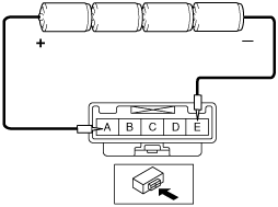
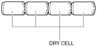
3. Prepare four dry cell batteries (1.5 V)
4. Connect the four dry cell batteries in a series.
ac5wzw00005108
|
5. Connect the positive pole of the dry cell battery to rear mount camera terminal A, and the negative pole to terminal E.
ac5wzw00004640
|
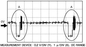
6. With the cell batteries being connected, measure the waveform between rear mount camera terminal E and terminal C.
7. Verify that waveform A shown in the figure is displayed two times or more.
ac9wzw00002991
|
8. If the voltage is not as shown in the figure, replace the rear mount camera. (See REAR MOUNT CAMERA REMOVAL/INSTALLATION.)
Predicted vehicle path assist lines display type
1. Disconnect the negative battery terminal. (See NEGATIVE BATTERY TERMINAL DISCONNECTION/CONNECTION.)
2. Remove the following parts:
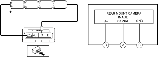
3. Connect the battery positive voltage to rear mount camera terminal A and connect terminal D to ground.
ac9wzw00004329
|
4. With the cell batteries being connected, measure the waveform between rear mount camera terminal E and terminal C.
5. Verify that waveform A shown in the figure is displayed two times or more.
ac9wzw00002991
|
6. If the voltage is not as shown in the figure, replace the rear mount camera. (See REAR MOUNT CAMERA REMOVAL/INSTALLATION.)
With 360°View Monitor System
1. Disconnect the negative battery terminal. (See NEGATIVE BATTERY TERMINAL DISCONNECTION/CONNECTION.)
2. Remove the following parts:
3. Prepare four dry cell batteries (1.5 V)
4. Connect the four dry cell batteries in a series.
ac5wzw00005108
|
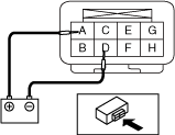
5. Connect the positive pole of the dry cell battery to rear mount camera terminal B, and the negative pole to terminal C.
ac8wzw00001263
|
6. With the cell batteries being connected, measure the waveform between rear mount camera terminal A and terminal C.
7. Verify that waveform A shown in the figure is displayed two times or more.
ac9wzw00002991
|
8. If the voltage is not as shown in the figure, replace the rear mount camera. (See REAR MOUNT CAMERA REMOVAL/INSTALLATION.)