-
Note
-
• If double-sided adhesive tape remains on the liftgate, warm the tape using a drier and then remove it using a resin spatula.
 ac9uuw00007038
REAR FINISHER INSTALLATION
id091600969000
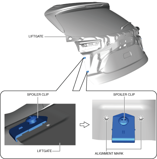
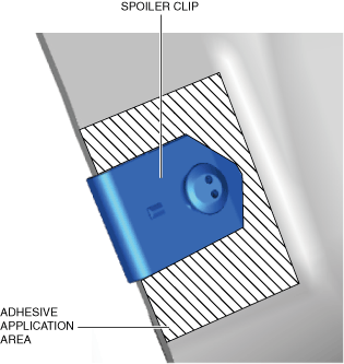
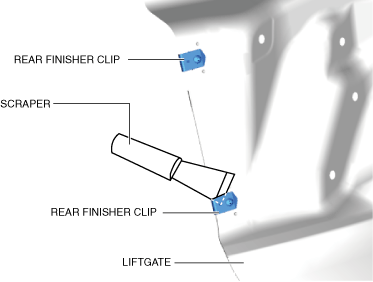
1. If a rear finisher clips has been damaged, perform the following procedure:
ac9uuw00007038
|
ac9wzw00004776
|
ac9uuw00007040
|
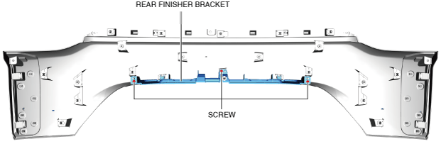
2. Install the rear finisher bracket.
3. Install the screws to the rear finisher bracket.
ac9uuw00007041
|
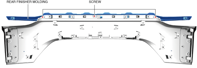
4. Install the rear finisher molding.
5. Install the screws.
ac9uuw00007042
|
6. Install the rear mount camera. (With rear mount camera) (See REAR MOUNT CAMERA REMOVAL/INSTALLATION.)
7. Install the request switch. (With advanced keyless entry system) (See REQUEST SWITCH REMOVAL/INSTALLATION.)
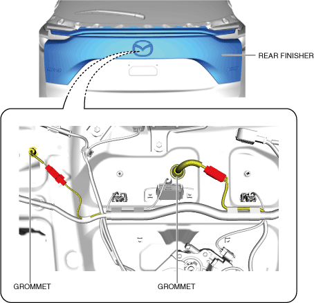
8. Install the grommet of the wiring harness. (With advanced keyless entry system) (With rear mount camera)
ac9uuw00007043
|
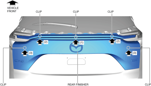
9. Press in the rear finisher in the direction of the arrows shown in the figure and install the clips to the liftgate.
ac9uuw00007044
|
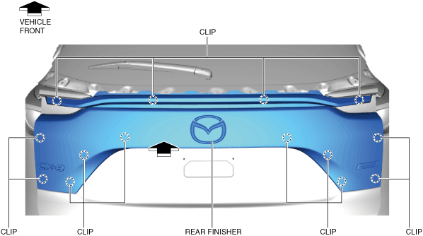
10. Move the rear finisher in the direction of the arrow shown in the figure and insert the clips to the liftgate.
ac9uuw00007045
|
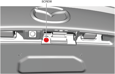
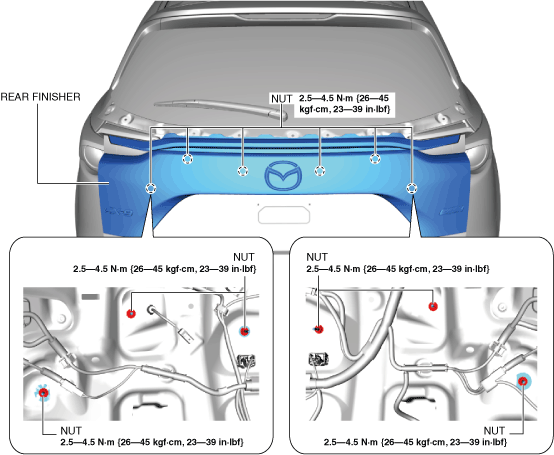
11. Install the screw.
ac9uuw00007046
|
12. Install the cap.
13. Install the nuts.
ac9wzw00004450
|
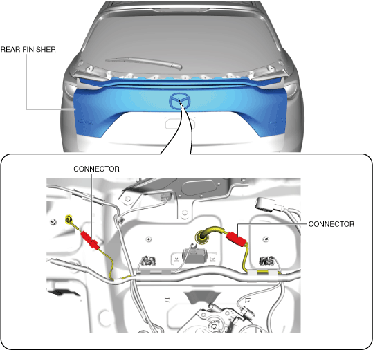
14. Connect the request switch connector. (With advanced keyless entry system)
ac9wzw00003952
|
15. Connect the rear mount camera connector. (With rear mount camera)
16. Install the liftgate garnish. (See LIFTGATE GARNISH REMOVAL/INSTALLATION.)
17. Install the following parts:
18. Connect the negative battery terminal. (See NEGATIVE BATTERY TERMINAL DISCONNECTION/CONNECTION.)
19. Perform the 360° view monitor system aiming. (With 360° view monitor system) (See 360°VIEW MONITOR SYSTEM AIMING.)
20. Perform the rear mount camera initialization (calibration). (With projected vehicle path line display and without 360° view monitor system) (See PARKING ASSIST SYSTEM INITIALIZATION (CALIBRATION).)