 |
ac9wzw00003992
DTC P0A12:00 [i-ELOOP]
id130201001800
Details On DTCs
|
DESCRIPTION |
DC-DC converter (i-ELOOP): low input |
|
|---|---|---|
|
DETECTION CONDITION
|
Determination conditions
|
• DC-DC converter (i-ELOOP) terminal 2A voltage is specified value or less.
|
|
Preconditions
|
• Ignition switched ON
|
|
|
Malfunction determination period
|
• 5 s period
|
|
|
Drive cycle
|
• 1
|
|
|
Self test type
|
• CMDTC self test, ODDTC self test
|
|
|
Sensor used
|
• DC-DC converter (i-ELOOP)
|
|
|
FAIL-SAFE FUNCTION
|
• Inhibits engine-stop by operating the i-stop function.
• Switches to bypass mode which shuts the capacitor (i-ELOOP) off.
|
|
|
VEHICLE STATUS WHEN DTCs ARE OUTPUT
|
• Flashes i-stop warning light (amber).
• A warning message is displayed on the center display.
• The following vehicle conditions differ depending on the type of malfunction
• If the vehicle continues to be driven while the DTC is detected the battery will be depleted.
|
|
|
POSSIBLE CAUSE
|
• Connector or terminal malfunction of the following parts:
• Short to ground in wiring harness between the following terminals:
• Open circuit in wiring harness between the following terminals:
• DC-DC converter (i-ELOOP) malfunction
|
|
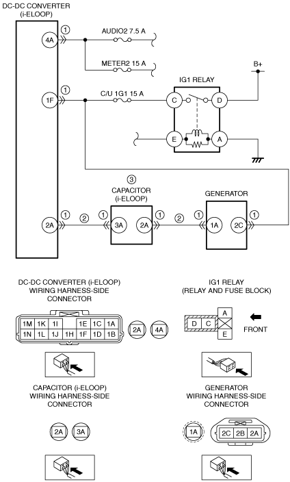
System Wiring Diagram
ac9wzw00003992
|
Function Explanation (DTC Detection Outline)
Repeatability Verification Procedure
PID Item/Simulation Item Used In Diagnosis
Function Inspection Using M-MDS
|
STEP |
INSPECTION |
RESULTS |
ACTION |
|---|---|---|---|
|
1
|
PURPOSE: VERIFY RELATED SERVICE INFORMATION AVAILABILITY
• Verify related Service Information availability.
• Is any related Service Information available?
|
Yes
|
Perform repair or diagnosis according to the available Service Information.
• If the vehicle is not repaired, go to the next step.
|
|
No
|
Go to the next step.
|
||
|
2
|
PURPOSE: VERIFY IF POWER SUPPLY IS AFFECTED BY DTC RELATED TO DC-DC CONVERTER (i-ELOOP)
• Switch the ignition off, then ON (engine off).
• Perform the DC-DC converter (i-ELOOP) DTC inspection using the M-MDS.
(See DTC INSPECTION [i-ELOOP].)
• Is the DTC P1628:11 or U3000:49 also present?
|
Yes
|
Go to the applicable DTC inspection.
(See DTC P1628:11 [i-ELOOP].)
(See DTC U3000:49 [i-ELOOP].)
Go to the next step.
|
|
No
|
Go to the next step.
|
||
|
3
|
PURPOSE: VERIFY IF POWER SUPPLY IS AFFECTED BY DTC RELATED TO PCM
• Perform the PCM DTC inspection using the M-MDS.
• Is the DTC P0A94:00 or P2503:00 also present?
|
Yes
|
Go to the applicable DTC inspection.
Go to the troubleshooting procedure to perform the procedure from Step 1.
|
|
No
|
Go to the troubleshooting procedure to perform the procedure from Step 1.
|
Troubleshooting Diagnostic Procedure
|
STEP |
INSPECTION |
RESULTS |
ACTION |
|---|---|---|---|
|
1
|
PURPOSE: VERIFY IF CONNECTOR DAMAGE OF EACH PART AFFECTS DIAGNOSTIC RESULTS
• Switch the ignition off.
• Disconnect the negative battery terminal.
• Remove the service plug.
• Disconnect the connector of the following parts.
• Inspect for poor connection (such as damaged/pulled-out pins, corrosion).
• Is there any malfunction?
|
Yes
|
Repair or replace the connector and/or terminals, then go to Step 3.
|
|
No
|
Go to the next step.
|
||
|
2
|
PURPOSE: VERIFY IF SHORT TO GROUND IN EACH WIRING HARNESS AFFECTS DIAGNOSTIC RESULTS
• Verify that the generator, capacitor (i-ELOOP), and DC-DC converter (i-ELOOP) connectors are disconnected.
• Inspect for continuity between the following terminals (wiring harness-side) and body ground:
• Is there continuity?
|
Yes
|
Refer to the wiring diagram and verify whether or not there is a common connector between the following terminals:
• Capacitor (i-ELOOP) terminal 2A—Generator terminal 1A
• Capacitor (i-ELOOP) terminal 3A—DC-DC converter (i-ELOOP) terminal 2A
If there is a common connector:
• Determine the malfunctioning part by inspecting the common connector and the terminal for corrosion, damage, or pin disconnection, and the common wiring harness for a short to ground.
• Repair or replace the malfunctioning part.
If there is no common connector:
• Repair or replace the wiring harness which has a short to ground.
Go to the next step.
|
|
No
|
Go to Step 4.
|
||
|
3
|
PURPOSE: INSPECT CAPACITOR (i-ELOOP) FOR MALFUNCTION DEPENDING ON REPEATABILITY
• Always reconnect all disconnected connectors.
• Reinstall the service plug.
• Reconnect the negative battery terminal.
• Clear the DTC for the DC-DC converter (i-ELOOP) using the M-MDS.
(See CLEARING DTC [i-ELOOP].)
• Implement the repeatability verification procedure.
• Retrieve the DC-DC converter (i-ELOOP) DTCs using the M-MDS.
(See DTC INSPECTION [i-ELOOP].)
• Is the same DTC present?
|
Yes
|
Replace the capacitor (i-ELOOP).
Go to Step 6.
|
|
No
|
Go to Step 7.
|
||
|
4
|
PURPOSE: VERIFY IF MALFUNCTION OCCURRING IS CAUSED BY WIRING HARNESS/CONNECTOR LOSS
• Have all the wiring harnesses/connectors which can be considered the cause of DTC P0A12:00 been inspected?
|
Yes
|
Go to the next step.
|
|
No
|
Inspect all the related wiring harnesses/connectors.
• If there is any malfunction:
• If there is no malfunction:
|
||
|
5
|
PURPOSE: VERIFY DC-DC CONVERTER (i-ELOOP) REPLACEMENT RECORD
• Is the DC-DC converter (i-ELOOP) being replaced within the troubleshooting diagnostic procedure this time?
|
Yes
|
Go to the next step.
|
|
No
|
Replace the DC-DC converter (i-ELOOP).
Go to the next step.
|
||
|
6
|
PURPOSE: VERIFICATION OF VEHICLE REPAIR COMPLETION
• Always reconnect all disconnected connectors.
• Reinstall the service plug.
• Reconnect the negative battery terminal.
• Start the engine and leave for 100 s or more.
• Clear the DTC for the DC-DC converter (i-ELOOP) using the M-MDS.
(See CLEARING DTC [i-ELOOP].)
• Implement the repeatability verification procedure.
• Retrieve the DC-DC converter (i-ELOOP) DTCs using the M-MDS.
(See DTC INSPECTION [i-ELOOP].)
• Is the same DTC present?
|
Yes
|
Repeat the inspection from Step 4.
|
|
No
|
Go to the next step.
|
||
|
7
|
PURPOSE: VERIFY IF THERE IS ANY OTHER MALFUNCTION
• Is any other DTC or pending code stored?
|
Yes
|
Go to the applicable DTC inspection.
(See DTC TABLE [i-ELOOP].)
|
|
No
|
DTC troubleshooting completed.
|