49 B025 017
Sliding hammer

49 B025 010
Attachment A

REAR DRIVE SHAFT REMOVAL/INSTALLATION
id031300145000
Special Service Tool (SST)
|
49 B025 017
Sliding hammer
|
|
49 B025 010
Attachment A
|
|
1. Switch the ignition ON (engine off).
2. Release the electric parking brake.
3. Switch the ignition off.
4. Disconnect the negative battery terminal. (See NEGATIVE BATTERY TERMINAL DISCONNECTION/CONNECTION.)
5. Remove the wheel and tire. (See WHEEL AND TIRE REMOVAL/INSTALLATION.)
6. Drain the differential oil. (See DIFFERENTIAL OIL REPLACEMENT.)
7. When working on the left side of the vehicle, disconnect the auto leveling sensor link. (With auto leveling sensor)
ac4ccw00000647
|
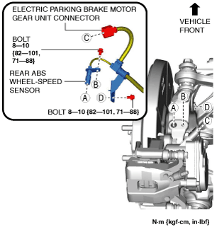
8. Disconnect the rear ABS wheel-speed sensor wiring harness and the electric parking brake motor gear unit connector and set it aside so that it does not interfere with the servicing.
ac9uuw00008046
|
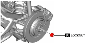
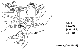
9. Remove the locknut. (See Locknut Removal Note.) (See Locknut Installation Note.)
ac9uuw00008047
|
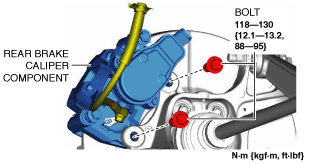
10. Remove the rear brake caliper component installation bolts.
ac9uuw00008048
|
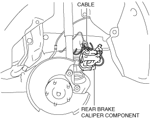
11. Remove the rear brake caliper component and suspend it out of the way using a cable.
ac9uuw00008049
|
12. Remove the rear disc plate. (See REAR BRAKE (DISC) REMOVAL/INSTALLATION.)
13. Remove the wheel hub component. (See WHEEL HUB COMPONENT REMOVAL/INSTALLATION [4WD].)
14. Remove the dust cover. (See WHEEL HUB COMPONENT REMOVAL/INSTALLATION [4WD].)
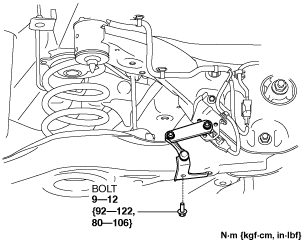
15. Disconnect the rear stabilizer control link from the rear lower arm.
ac9uuw00008050
|
16. Disconnect the rear trailing link from the hub support. (See REAR TRAILING LINK REMOVAL/INSTALLATION.)
17. Remove the rear coil spring. (See REAR COIL SPRING REMOVAL/INSTALLATION.)
18. Disconnect the rear shock absorber from the hub support. (See REAR SHOCK ABSORBER REMOVAL/INSTALLATION.)
19. Disconnect the rear lateral link from the hub support. (See REAR LATERAL LINK REMOVAL/INSTALLATION.)
20. Disconnect the rear upper arm from the hub support. (See REAR UPPER ARM REMOVAL/INSTALLATION [4WD].)
21. Remove the hub support. (See WHEEL HUB COMPONENT REMOVAL/INSTALLATION [4WD].)
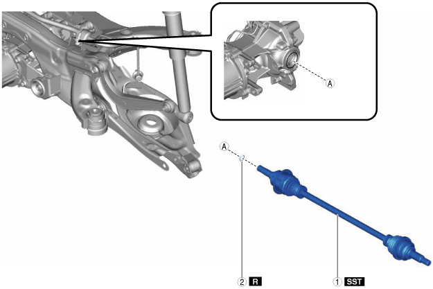
22. Remove in the order shown in the figure.
23. Install in the reverse order of removal. (See Suspension Links Installation Note.)
24. Add differential oil. (See DIFFERENTIAL OIL REPLACEMENT.)
25. Perform the headlight auto leveling system initial setting. (With auto leveling sensor) (See HEADLIGHT AUTO LEVELING SYSTEM INITIALIZATION.)
ac9uuw00008051
|
|
1
|
Rear drive shaft
|
|
2
|
Rear drive shaft clip
|
Locknut Removal Note
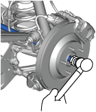
1. Remove the locknut with the brake pedal depressed.
2. Install a spare nut onto the drive shaft.
3. Tap the nut with a copper hammer and separate the drive shaft from the axle.
ac9uuw00010015
|
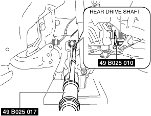
Rear Drive Shaft Removal Note
1. Set the SST (49 B025 010) to the rear drive shaft.
ac9uuw00008052
|
2. Install the SST (49 B025 017) to the SST (49 B025 010).
3. Disengage the rear drive shaft from the rear differential using the SST.
4. Remove the rear drive shaft.
Suspension Links Installation Note
1. When installing the joint sections with rubber bushings, perform the following procedures.
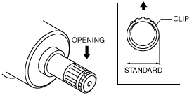
Rear Drive Shaft Clip Installation Note
1. Install a new clip to the clip groove at the end of the rear drive shaft with the clip opening facing upward.
amxuuw00004757
|
2. Verify that the outer diameter of the clip is within the specification.
Rear Drive Shaft Installation Note
1. Apply differential oil to the oil seal lip.
2. Install the rear drive shaft to the rear differential.
3. After installation, verify that the rear drive shaft is securely held by the clip by pulling the outer ring on the rear differential side towards the axle side.
Locknut Installation Note
1. If dust or grease is on the drive shaft thread area, wipe it off with a cloth.
2. Tighten the locknut using the following procedure and with the brake pedal depressed.