ac9uuw00005905
|
AUTOMATIC TRANSAXLE SHIFT MECHANISM REMOVAL/INSTALLATION
id051800296900
Selector Lever Component Removal/Installation
1. Disconnect the negative battery terminal. (See NEGATIVE BATTERY TERMINAL DISCONNECTION/CONNECTION.)
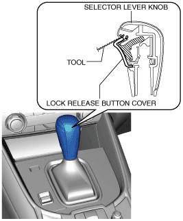
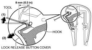
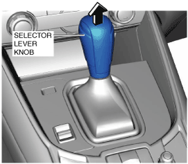
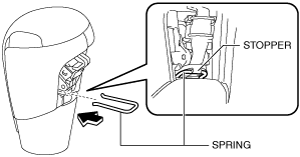
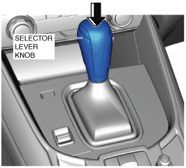
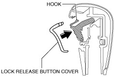
2. Perform the following procedure to remove the selector lever knob.
ac9uuw00005905
|
ac9uuw00005906
|
am6zzw00012088
|
ac9uuw00005907
|
3. Remove the following parts:
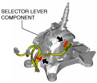
4. Disconnect the wiring harness clip from the selector lever component.
ac9uuw00007094
|
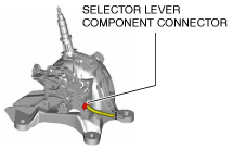
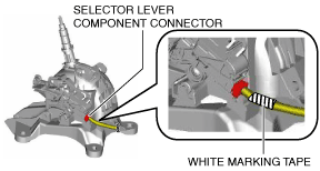
5. Disconnect the selector lever component connector.
ac9uuw00006136
|
6. Disconnect the selector cable (selector lever side). (See Selector Cable Removal/Installation.)
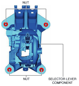
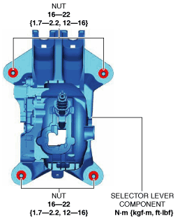
7. Remove the nuts from the selector lever component.
ac9uuw00005909
|
8. Remove the selector lever component.
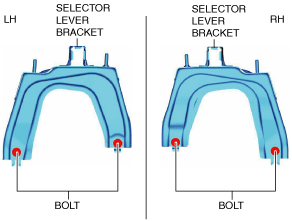
9. Remove the selector lever bracket.
ac9uuw00005910
|
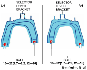
10. Install the selector lever bracket.
ac9uuw00005917
|
11. Install the selector lever component.
12. Install the nuts to the selector lever component.
ac9uuw00005912
|
13. Connect the selector cable (selector lever side). (See Selector Cable Removal/Installation.)
14. Connect the selector lever component connector.
ac9uuw00005913
|
15. Connect the wiring harness clip to the selector lever component.
ac9uuw00007094
|
16. Install the following parts:
17. Perform the following procedure to install the selector lever knob.
am6zzw00012090
|
ac9uuw00005914
|
am6zzw00012092
|
18. Connect the negative battery terminal. (See NEGATIVE BATTERY TERMINAL DISCONNECTION/CONNECTION.)
Indicator Removal/Installation
1. Disconnect the negative battery terminal. (See NEGATIVE BATTERY TERMINAL DISCONNECTION/CONNECTION.)
2. Remove the following parts:
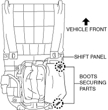
3. Turn over the removed shift panel and remove the boots from the boots securing parts shown in the figure.
ac9uuw00005903
|
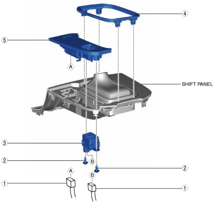
4. Remove in the order indicated in the table.
5. Install in the reverse order of removal.
ac9uuw00005915
|
|
1
|
Connector
|
|
2
|
Screw
|
|
3
|
Drive selection switch
|
|
4
|
Indicator panel
|
|
5
|
Indicator
(See Indicator removal note.)
|
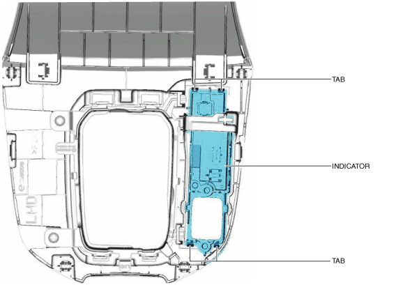
Indicator removal note
1. Detach tabs shown in the figure and remove the indicator.
ac9uuw00005916
|
Selector Cable Removal/Installation
1. Disconnect the negative battery terminal. (See NEGATIVE BATTERY TERMINAL DISCONNECTION/CONNECTION.)
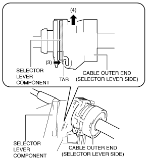
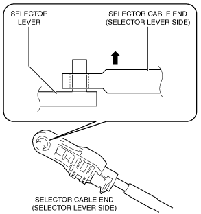
2. Perform the following procedure to remove the selector cable (selector lever side).
ac9uuw00007714
|
ac9wzw00004936
|
ac5wzw00001125
|
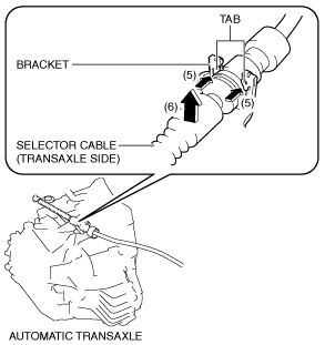
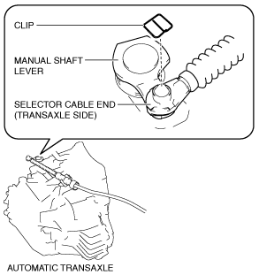
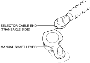
3. Perform the following procedure to remove the selector cable (transaxle side).
ac5wzw00000934
|
ac5uuw00009245
|
ac5wzw00000932
|
ac5wzw00000933
|
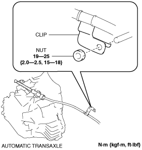
4. Disconnect the clip as shown in the figure and remove the nut.
ac5wzw00002164
|
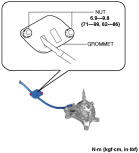
5. Disconnect the grommet as shown in the figure and remove the nuts.
ac9uuw00007715
|
6. Pull out the selector cable from inside the cabin and remove it.
7. Install in the reverse order of removal.
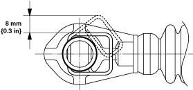
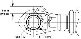
Selector cable end (transaxle side) installation note
ac5uuw00009246
|
1. Install a clip to the groove of the selector cable end (transaxle side).
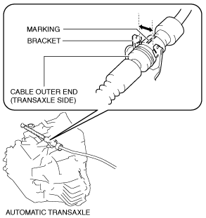
Cable outer end (transaxle side) installation note
1. Assemble the cable outer end (transaxle side) to the bracket so that the marking is in the area of the arrow shown in the figure.
ac5wzw00001128
|
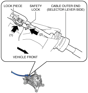
Selector cable (selector lever side) installation note
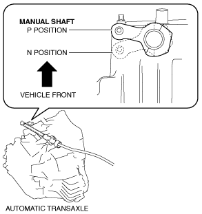
1. Verify that the selector lever is in the P position.
2. Verify that the manual shaft is in the P position.
ac5wzw00001126
|
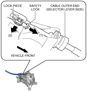
3. Press in the lock piece in the direction of the arrow (1) shown in the figure, press in the safety lock in the direction of the arrow (2) shown in the figure, and lock it.
ac9uuw00007716
|
Selector Cable Adjustment
1. Disconnect the negative battery terminal. (See NEGATIVE BATTERY TERMINAL DISCONNECTION/CONNECTION.)
2. Remove the following parts:
3. Shift the selector lever to the P position.
4. Pull out the safety lock in the direction of the arrow (1) shown in the figure, pull out the lock piece in the direction of the arrow (2) shown in the figure, and release the lock. (See Selector cable (selector lever side) installation note.)
ac9uuw00007714
|
5. Set the manual shaft to the P position.
ac5wzw00001126
|
6. Press in the lock piece in the direction of the arrow (1) shown in the figure, press in the safety lock in the direction of the arrow (2) shown in the figure, and lock it.
ac9uuw00007716
|
7. Perform the procedure in the reverse order of Step 1 to 2 to install the removed part.
8. Perform the selector lever inspection. (See SELECTOR LEVER INSPECTION.)
Selector cable (selector lever side) installation note
1. Verify that the selector lever is in the P position.
2. Verify that the manual shaft is in the P position.
ac5wzw00001126
|
3. Press in the lock piece in the direction of the arrow (1) shown in the figure, press in the safety lock in the direction of the arrow (2) shown in the figure, and lock it.
ac9uuw00007716
|