|
1
|
DETERMINE IF MALFUNCTION CAUSE IS HEATED STEERING WHEEL SWITCH
• Operate the heated steering wheel switch to turn on the heated steering wheel system.
• Does the heated steering wheel switch LED illuminate?
|
Yes
|
Go to the next step.
|
|
No
|
Inspect the indicator unit, then go to step 14.
|
|
2
|
INSPECT IG1 RELAY
• Inspect the IG1 relay.
• Is the relay normal?
|
Yes
|
Go to the next step.
|
|
No
|
Inspect the IG1 relay, then go to step 14.
|
|
3
|
INSPECT HEATED STEERING WHEEL CONTROL UNIT POWER SUPPLY FUSE
• Inspect the C/U IG1 15 A fuse.
• Is the fuse normal?
|
Yes
|
Go to the next step.
|
|
No
|
• If the fuse is deterioration:
-
? Replace the malfunctioning fuse.
• If the fuse is blown: Repair the short to ground in wiring harness between the following terminals:
-
? C/U IG1 15 A fuse and heated steering wheel relay terminal A
• Go to step 14.
|
|
4
|
INSPECT HEATED STEERING WHEEL CONTROL UNIT POWER SUPPLY FUSE
• Inspect the ST.HEATER 15 A fuse.
• Is the fuse normal?
|
Yes
|
Go to the next step.
|
|
No
|
• If the fuse is deterioration:
-
? Replace the malfunctioning fuse.
• If the fuse is blown: Repair the short to ground in wiring harness between the following terminals:
-
? ST.HEATER 15 A fuse and heated steering wheel relay terminal D
• Go to step 14.
|
|
5
|
INSPECT HEATED STEERING WHEEL RELAY
• Inspect the heated steering wheel relay.
• Is the relay normal?
|
Yes
|
Go to the next step.
|
|
No
|
Inspect the heated steering wheel relay, then go to step 14.
|
|
6*
|
VERIFY IF MALFUNCTION CAUSE IS HEATED STEERING WHEEL CONTROL UNIT POWER SUPPLY CIRCUIT
-
Warning
-
• Handling the component parts improperly can accidentally operate (deploy) the air bag module, which may seriously injure you. Read the service warnings/cautions and the workshop manual before handling the air bag system components.
• Switch the ignition off (LOCK).
• Remove the driver-side air bag module connector.
• Remove the steering wheel.
• Remove the column cover.
• Remove the clock spring.
• Connect the negative battery terminal.
• Switch the ignition ON (engine off or on).
• Measure the voltage at the following terminals (vehicle wiring harness side).
-
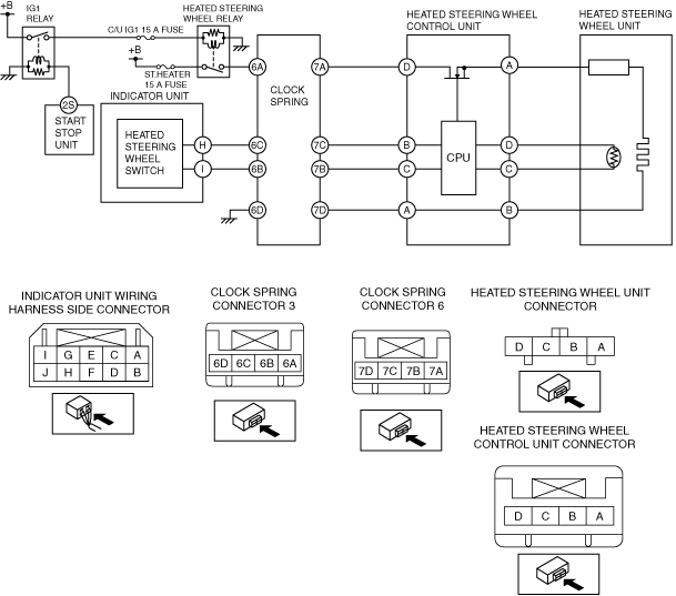
? Clock spring connector 3 terminal 6A
• Is the voltage B+?
|
Yes
|
Go to the next step.
|
|
No
|
• Refer to the wiring diagram and verify if there is a common wiring harness between the following terminal.
-
? Heated steering wheel relay terminal C and clock spring connector 3 terminal 6A
If there is a common connector:
-
• Inspect the common connector and terminals for corrosion, damage, or disconnection and the common wiring harnesses for short to ground to determine the malfunctioning location.
• Repair or replace the malfunctioning location.
If there is no common connector:
-
• Repair or replace the wiring harness which is shorted to ground.
• Replace the fuse.
Go to Step 14.
|
|
7*
|
VERIFY IF MALFUNCTION CAUSE IS OPEN CIRCUIT IN WIRING HARNESS BETWEEN CLOCK SPRING CONNECTOR AND BODY GROUND
• Switch the ignition OFF (LOCK).
• Verify that the clock spring connector 3 is disconnected.
• Inspect for continuity between the following terminals (vehicle wiring harness side) and body ground.
-
? Clock spring connector 3 terminal 6D
• Is there continuity?
|
Yes
|
Go to the next step.
|
|
No
|
• Refer to the wiring diagram and verify if there is a common connector between the following terminals and body ground.
-
? Clock spring connector 3 terminal 6D
If there is a common connector:
-
• Inspect the common connector and terminals for corrosion, damage, or disconnection and the common wiring harnesses for an open circuit to determine the malfunctioning location.
• Repair or replace the malfunctioning location.
If there is no common connector:
-
• Repair or replace the wiring harness which has an open circuit.
• Go to Step 14.
|
|
8*
|
VERIFY IF MALFUNCTION CAUSE IS SHORT CIRCUIT TO GROUND IN WIRING HARNESS BETWEEN CLOCK SPRING CONNECTOR AND INDICATOR UNIT
• Verify that the clock spring connector 3 is disconnected.
• Disconnect the indicator unit connector.
• Inspect for continuity between clock spring connector 3 terminal 6B (vehicle wiring harness side) and body ground.
• Is there continuity?
|
Yes
|
• Refer to the wiring diagram and verify if there is a common connector between clock spring connector 3 terminal 6B and indicator unit terminal I.
If there is a common connector:
-
? Inspect the common connector and terminals for corrosion, damage, or disconnection and the common wiring harnesses for short to ground to determine the malfunctioning location.
? Repair or replace the malfunctioning location.
If there is no common connector:
-
? Repair or replace the wiring harness which is shorted to ground.
• Go to Step 14.
|
|
No
|
Go to the next step.
|
|
9*
|
VERIFY IF MALFUNCTION CAUSE IS OPEN CIRCUIT IN WIRING HARNESS BETWEEN CLOCK SPRING CONNECTOR AND INDICATOR UNIT
• Verify that the clock spring connector 3 and the indicator unit connector are disconnected.
• Inspect the wiring harness for continuity between clock spring connector 3 terminal 6B and indicator unit terminal I (vehicle wiring harness side).
• Is there continuity?
|
Yes
|
Go to the next step.
|
|
No
|
• Refer to the wiring diagram and verify if there is a common connector between clock spring connector 3 terminal 6B and indicator unit terminal I.
If there is a common connector:
-
? Inspect the common connector and terminals for corrosion, damage, or disconnection and the common wiring harnesses for an open circuit to determine the malfunctioning location.
? Repair or replace the malfunctioning location.
If there is no common connector:
-
? Repair or replace the wiring harness which has an open circuit.
• Go to Step 14.
|
|
10*
|
DETERMINE IF CAUSE OF MALFUNCTION IS CLOCK SPRING
• Inspect for continuity between the following terminals:
-
? Clock spring connector 3 terminal 6A and 7A
? Clock spring connector 3 terminal 6B and 7B
? Clock spring connector 3 terminal 6D and 7D
• Is there continuity?
|
Yes
|
Go to the next step.
|
|
No
|
• Inspect the clock spring, then go to step 14.
|
|
11*
|
VERIFY IF MALFUNCTION CAUSE IS OPEN CIRCUIT IN WIRING HARNESS BETWEEN CLOCK SPRING AND HEATED STEERING WHEEL CONTROL UNIT
• Verify that the heated steering wheel control unit connector (clock spring side) is disconnected.
• Disconnect the is heated steering wheel control unit connector (unit side).
• Inspect for continuity between the following terminals.
-
? Heated steering wheel control unit harness connector terminal 7A and D
? Heated steering wheel control unit harness connector terminal 7B and C
? Heated steering wheel control unit harness connector terminal 7D and A
• Is there continuity?
|
Yes
|
Go to the next step.
|
|
No
|
Repair or replace the wiring harness which has an open circuit, then go to step 14.
|
|
12*
|
VERIFY IF MALFUNCTION CAUSE IS OPEN CIRCUIT IN WIRING HARNESS OF HEATED STEERING WHEEL UNIT CIRCUIT
• Inspect for continuity between the following terminals (wiring harness-side);
-
? Heated steering wheel unit terminal A and B
? Heated steering wheel unit terminal C and D
• Is there continuity?
|
Yes
|
Go to the next step.
|
|
No
|
Repair or replace the wiring harness which has an open circuit, then go to the next step.
|
|
13
|
DETERMINE IF MALFUNCTION CAUSE IS HEATED STEERING WHEEL CONTROL UNIT
• Reconnect all the disconnected connectors.
• Connect the negative battery terminal.
• Switch the ignition ON (engine off or on).
• Operate the heated steering wheel switch to turn on the heated steering wheel system.
• Does the seat warmer system operate normally?
|
Yes
|
Go to the next step.
|
|
No
|
Replace the heated steering wheel control unit, then go to the next step.
|
|
14
|
VERIFY IF MALFUNCTION CAUSE IS CORRECTED
• Operate the heated steering wheel switch to turn on the heated steering wheel system.
• Does the seat warmer system operate normally?
|
Yes
|
Troubleshooting completed. (Explain the contents of the servicing to the customer.)
|
|
No
|
Verify the malfunction symptom in the symptom troubleshooting chart and perform the other applicable malfunction diagnosis.
|