 |
am2zzw00011535
INDICATOR UNIT INSPECTION
id092200037600
Terminal Voltage Inspection
1. Disconnect the negative battery terminal. (See NEGATIVE BATTERY TERMINAL DISCONNECTION/CONNECTION.)
2. Remove the following parts:
3. Remove the indicator unit with the connector still connected. (See INDICATOR UNIT REMOVAL/INSTALLATION.)
4. Connect the negative battery terminal. (See NEGATIVE BATTERY TERMINAL DISCONNECTION/CONNECTION.)
5. Verify that the voltages of each of the terminals are as indicated in the terminal voltage table (reference).
Terminal Voltage Table (Reference)
am2zzw00011535
|
|
Terminal |
Signal name |
Connected to |
Measurement conditions |
Voltage (V) |
Inspection item(s) |
|
|---|---|---|---|---|---|---|
|
A
|
Power supply (IG1)
|
IG1 relay
|
Ignition switch ON (engine off or on)
|
B+
|
• METER1 10A fuse
• IG1 relay
• Related wiring harness
|
|
|
Ignition switch off or ACC
|
1.0 or less
|
|||||
|
B
|
Power supply
|
• INTERIOR 10 A fuse
• ROOM 25 A fuse
|
Under any condition
|
B+
|
• INTERIOR 10 A fuse
• ROOM 25 A fuse
• Battery
• Related wiring harness
|
|
|
C
|
Power supply (IG1)*1
|
Ignition relay (IG1_STAB)
|
Ignition switch ON (engine off or on)
|
B+
|
• Ignition relay (IG1_STAB)
• Related wiring harness
|
|
|
Ignition switch off or ACC
|
1.0 or less
|
|||||
|
Power supply (IG1)*2
|
IG1 relay
|
Ignition switch ON (engine off or on)
|
B+
|
• C/U IG1 15A fuse
• IG1 relay
• Related wiring harness
|
||
|
Ignition switch off or ACC
|
1.0 or less
|
|||||
|
D*3
|
Seat warmer switch signal
|
Seat warmer control unit
|
Because this terminal is for communication, determination using terminal voltage inspection is not possible.
|
|||
|
E
|
—
|
—
|
—
|
—
|
—
|
|
|
F
|
Ground
|
Body ground
|
Under any condition
|
1.0 or less
|
• Body ground
• Related wiring harness
|
|
|
G
|
Instrument cluster signal
|
Instrument cluster
|
Because this terminal is for communication, determination using terminal voltage inspection is not possible.
|
|||
|
H*4
|
Heated steering wheel indicator
|
Heated steering wheel control unit
|
Ignition switched ON (engine off)
|
Heated steering wheel is not operating
|
B+
|
• Heated steering wheel control unit
• Related wiring harness
|
|
Heated steering wheel is operating
|
1.0 or less
|
|||||
|
I*4
|
Heated steering wheel switch signal
|
Heated steering wheel control unit
|
Ignition switched ON (engine off)
|
Heated steering wheel switch pressed
|
B+
|
• Heated steering wheel control unit
• Related wiring harness
|
|
Heated steering wheel switch released
|
1.0 or less
|
|||||
|
J
|
—
|
—
|
—
|
—
|
—
|
|
LED Illumination Inspection
When using M-MDS
1. Connect the M-MDS to the DLC-2.
2. After the vehicle is identified, select the following items from the initialization screen of the M-MDS.
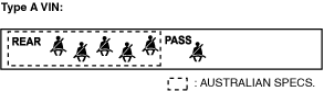
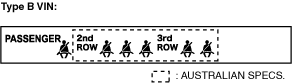
3. Using the simulation function item LCD_SEG, verify that the warning/indicator lights are displayed as shown in the following figure.
ac9wzw00005433
|
ac9wzw00005434
|
When not using M-MDS
1. Disconnect the negative battery terminal. (See NEGATIVE BATTERY TERMINAL DISCONNECTION/CONNECTION.)
2. Remove the following parts:
3. Remove the indicator unit with the connector still connected. (See INDICATOR UNIT REMOVAL/INSTALLATION.)
4. Connect the negative battery terminal. (See NEGATIVE BATTERY TERMINAL DISCONNECTION/CONNECTION.)
5. Switch the ignition ON (engine off or on).
6. Using a jumper wire, connect indicator unit terminal G and body ground for 5 s or more.
am2zzw00011535
|
7. Verify that the following warning/indicator lights are turned on.
ac9wzw00005433
|
ac9wzw00005434
|