|
1
|
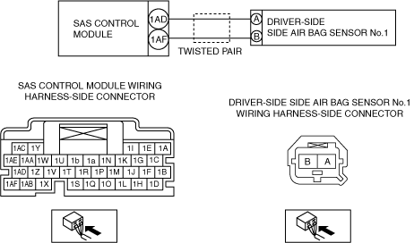
INSPECT DRIVER-SIDE SIDE AIR BAG SENSOR NO.1 CONNECTOR
-
Warning
-
• Handling the component parts improperly can accidentally operate (deploy) the air bag module, which may seriously injure you. Read the service warnings/cautions and the workshop manual before handling the air bag system components.
• Switch the ignition off.
• Inspect the driver-side side air bag sensor No.1 connector (wiring harness-side). (Corrosion, damage, and disconnected pins)
• Is there any malfunction of the driver-side side air bag sensor No.1 connector (wiring harness-side)?
|
Yes
|
Replace the malfunctioning part, then go to Step 5.
|
|
No
|
Go to the next step.
|
|
2
|
INSPECT DRIVER-SIDE SIDE AIR BAG SENSOR NO.1 CIRCUIT FOR SHORT TO GROUND
• Inspect for continuity between the following terminals (wiring harness-side) and body ground:
-
? SAS control module terminal 1AD
? SAS control module terminal 1AF
-
Note
-
• Inspect for continuity while shaking the wiring harness between the SAS control module and driver-side side air bag sensor No.1.
• Is there continuity?
|
Yes
|
Refer to the wiring diagram and verify whether or not there is a common connector between SAS control module terminal and driver-side side air bag sensor No.1 terminal.
If there is a common connector:
• Determine the malfunctioning part by inspecting the common connector and the terminal for corrosion, damage, or pin disconnection, and the common wiring harness for a short to ground.
• Replace the malfunctioning part.
If there is no common connector:
• Replace the wiring harness which has a short to ground.
Go to Step 5.
|
|
No
|
Go to the next step.
|
|
3
|
INSPECT DRIVER-SIDE SIDE AIR BAG SENSOR NO.1 CIRCUIT FOR OPEN CIRCUIT
• Driver-side side air bag sensor No.1 and SAS control module connectors are disconnected.
• Inspect for continuity between the following terminals (wiring harness-side):
-
? Driver-side side air bag sensor No.1 terminal A—SAS control module terminal 1AD
? Driver-side side air bag sensor No.1 terminal B—SAS control module terminal 1AF
-
Note
-
• Inspect for continuity while shaking the wiring harness between the SAS control module and driver-side side air bag sensor No.1.
• Is there continuity?
|
Yes
|
Go to the next step.
|
|
No
|
Refer to the wiring diagram and verify whether or not there is a common connector between SAS control module terminal and driver-side side air bag sensor No.1 terminal.
If there is a common connector:
• Determine the malfunctioning part by inspecting the common connector and the terminal for corrosion, damage, or pin disconnection, and the common wiring harness for an open circuit.
• Replace the malfunctioning part.
If there is no common connector:
• Replace the wiring harness which has an open circuit.
Go to Step 5.
|
|
4
|
INSPECT DRIVER-SIDE SIDE AIR BAG SENSOR NO.1 CIRCUIT FOR SHORT TO POWER SUPPLY
• Driver-side side air bag sensor No.1 and SAS control module connectors are disconnected.
• Switch the ignition ON (engine off or on).
• Measure the voltage at the following terminals (wiring harness-side):
-
? SAS control module terminal 1AD
? SAS control module terminal 1AF
-
Note
-
• Measure the voltage while shaking the wiring harness between the SAS control module and driver-side side air bag sensor No.1.
• Is the voltage 0 V?
|
Yes
|
Replace the driver-side side air bag sensor No.1, then go to the next step. (See SIDE AIR BAG SENSOR NO. 1 REMOVAL/INSTALLATION.) |
|
No
|
Refer to the wiring diagram and verify whether or not there is a common connector between SAS control module terminal and driver-side side air bag sensor No.1 terminal.
If there is a common connector:
• Determine the malfunctioning part by inspecting the common connector and the terminal for corrosion, damage, or pin disconnection, and the common wiring harness for a short to power supply.
• Replace the malfunctioning part.
If there is no common connector:
• Replace the wiring harness which has a short to power supply.
Go to the next step.
|
|
5
|
PERFORM SAS CONTROL MODULE DTC INSPECTION
• Switch the ignition off.
• Disconnect the negative battery terminal and wait for 1 min or more.
• Connect the SAS control module connectors.
• Reconnect all disconnected connectors.
• Switch the ignition ON (engine off or on).
• Are the same DTCs displayed?
|
Yes
|
Repeat the inspection from Step 1.
|
|
No
|
DTC troubleshooting completed.
|