 |
ac9uuw00007406
POWER LIFTGATE (PLG) CONTROL MODULE INSPECTION
id091100804300
1. Disconnect the negative battery terminal. (See NEGATIVE BATTERY TERMINAL DISCONNECTION/CONNECTION.)
2. Remove the following parts:
3. Connect the negative battery terminal. (See NEGATIVE BATTERY TERMINAL DISCONNECTION/CONNECTION.)
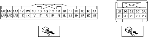
4. Verify that the voltages of each of the terminals are as indicated in the terminal voltage table (reference).
Terminal Voltage Table (Reference)
ac9uuw00007406
|
|
Terminal |
Signal name |
Connected to |
Measurement condition |
Voltage (V)/Continuity |
Inspection item(s) |
|---|---|---|---|---|---|
|
1A
|
CAN_L
|
-
|
Because this terminal is for communication, good/no good judgment by terminal voltage is not possible
|
||
|
1B
|
CAN_H
|
-
|
Because this terminal is for communication, good/no good judgment by terminal voltage is not possible
|
||
|
1C
|
-
|
-
|
-
|
-
|
-
|
|
1D
|
Liftgate opener switch signal
|
Rear body control module (RBCM)
|
When the liftgate opener switch is ON
|
2.0 or less
|
Rear body control module (RBCM)
|
|
When the liftgate opener switch is OFF
|
5.0
|
||||
|
1D
|
-
|
-
|
-
|
-
|
-
|
|
1E
|
Hall effect switch ground (RH)
|
Power liftgate (PLG) drive unit (RH)
|
Under any condition
|
1.0 or less
|
Power liftgate (PLG) drive unit (RH)
|
|
1F
|
Hall effect switch ground (LH)
|
Power liftgate (PLG) drive unit (LH)
|
Under any condition
|
1.0 or less
|
Power liftgate (PLG) drive unit (LH)
|
|
1G
|
Hall effect switch No.1 (RH)
|
Power liftgate (PLG) drive unit (RH)
|
Liftgate is operating
|
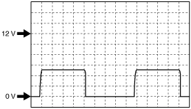
Wave pattern (See Inspection Using an Oscilloscope (Reference).)
|
Power liftgate (PLG) drive unit (RH)
|
|
1H
|
Hall effect switch No.1 (LH)
|
Power liftgate (PLG) drive unit (LH)
|
Liftgate is operating
|
Wave pattern (See Inspection Using an Oscilloscope (Reference).)
|
Power liftgate (PLG) drive unit (LH)
|
|
1I
|
Hall effect switch No.2 (RH)
|
Power liftgate (PLG) drive unit (RH)
|
Liftgate is operating
|
Wave pattern (See Inspection Using an Oscilloscope (Reference).)
|
Power liftgate (PLG) drive unit (RH)
|
|
1J
|
Hall effect switch No.2 (LH)
|
Power liftgate (PLG) drive unit (LH)
|
Liftgate is operating
|
Wave pattern (See Inspection Using an Oscilloscope (Reference).)
|
Power liftgate (PLG) drive unit (LH)
|
|
1K
|
Hall effect switch power supply (RH)
|
Power liftgate (PLG) drive unit (RH)
|
Under any condition
|
B+
|
Power liftgate (PLG) drive unit (RH)
|
|
1L
|
Hall effect switch power supply (LH)
|
Power liftgate (PLG) drive unit (LH)
|
Under any condition
|
B+
|
Power liftgate (PLG) drive unit (LH)
|
|
1M
|
Power liftgate (PLG) touch sensor GND
|
Body ground
|
Under any condition
|
1.0 or less
|
Related wiring harnesses
|
|
1N
|
Power liftgate (PLG) touch sensor signal (LH)
|
Power liftgate (PLG) touch sensor (LH)
|
When pressure is applied to the power liftgate (PLG) touch sensor (LH)
|
1.0 or less
|
Power liftgate (PLG) touch sensor (LH)
|
|
Other
|
B+
|
||||
|
1O
|
Full latch switch
|
Liftgate latch and lock actuator
|
After opening the liftgate, operate the closure motor with the liftgate half-closed
|
1.0 or less? B+? 1.0 or less
|
Liftgate latch and lock actuator
|
|
1P
|
Power liftgate (PLG) touch sensor signal (RH)
|
Power liftgate (PLG) touch sensor (RH)
|
When pressure is applied to the power liftgate (PLG) touch sensor (RH)
|
1.0 or less
|
Power liftgate (PLG) touch sensor (RH)
|
|
Other
|
B+
|
||||
|
1Q
|
Half latch switch
|
Liftgate latch and lock actuator
|
After opening the liftgate, operate the closure motor with the liftgate half-closed
|
1.0 or less? B+
|
Liftgate latch and lock actuator
|
|
1R
|
Power liftgate (PLG) buzzer output
|
Power liftgate (PLG) buzzer
|
When the power liftgate (PLG) buzzer is sounding
|
B+
|
Power liftgate (PLG) buzzer
|
|
Other
|
1.0 or less
|
||||
|
1S
|
Liftgate condition
|
Rear body control module (RBCM)
|
Liftgate closed
|
B+
|
Rear body control module (RBCM)
|
|
Other
|
1.0 or less
|
||||
|
1T
|
Motor return signal
|
Return switch
|
After opening the liftgate, operate the closure motor with the liftgate half-closed
|
1.0 or less
|
Liftgate latch and lock actuator
|
|
1U
|
Door lock (driver-side)
|
Door latch and lock actuator
|
The driver-side doors is unlocked
|
B+
|
Door latch and lock actuator
|
|
The driver-side doors is locked
|
1.0 or less
|
||||
|
1V
|
Door unlock (driver-side)
|
Door latch and lock actuator
|
The driver-side doors is unlocked
|
1.0 or less
|
Door latch and lock actuator
|
|
The driver-side doors is locked
|
B+
|
||||
|
1W
|
-
|
-
|
-
|
-
|
-
|
|
1X
|
Door unlock (passenger-side and rear)
|
Door latch and lock actuator
|
The passenger-side and rear doors are all unlocked
|
1.0 or less
|
Door latch and lock actuator
|
|
The passenger-side and rear doors are all locked
|
B+
|
||||
|
1Y
|
Power liftgate (PLG) front switch signal (Input)
|
Power liftgate (PLG) front switch
|
Power liftgate (PLG) front switch: Switch is at ON
|
B+
|
Power liftgate (PLG) front switch
|
|
Power liftgate (PLG) front switch: Switch is at OFF
|
1.0 or less
|
||||
|
1Z
|
Liftgate opener switch signal
|
Liftgate opener switch
|
When the liftgate opener switch is ON
|
B+
|
Liftgate opener switch
|
|
When the liftgate opener switch is OFF
|
1.0 or less
|
||||
|
1AA
|
Power supply
|
INTERIOR 20 A fuse
|
Under any condition
|
B+
|
INTERIOR 20 A fuse
|
|
1AB
|
-
|
-
|
-
|
-
|
-
|
|
1AC
|
Power supply to power liftgate (PLG) switches
|
Power liftgate (PLG) switch
|
Power liftgate (PLG) front switch: Open or close switch is at ON
|
1.0 or less
|
Power liftgate (PLG) control module
|
|
Power liftgate (PLG) front switch: Open or close switch is at OFF
|
B+
|
||||
|
1AD
|
Power supply
|
C/U IG1 15 A fuse
|
Ignition switched ON (engine off or on)
|
B+
|
C/U IG1 15 A fuse
|
|
Ignition switched off or at ACC
|
1.0 or less
|
||||
|
1AE
|
-
|
-
|
-
|
-
|
-
|
|
1AF
|
Power liftgate (PLG) rear switch signal
|
Power liftgate (PLG) rear switch
|
When operating the power liftgate (PLG) rear switch
|
B+
|
Power liftgate (PLG) rear switch
|
|
When not operating the power liftgate (PLG) rear switch
|
1.0 or less
|
||||
|
2A
|
Drive unit (LH) control open signal
|
Power liftgate (PLG) drive unit (LH)
|
Liftgate open operation
|
B+
|
Power liftgate (PLG) drive unit (LH)
|
|
Other
|
1.0 or less
|
||||
|
2B
|
Drive unit (RH) control close signal
|
Power liftgate (PLG) drive unit (RH)
|
Liftgate close operation
|
B+
|
Power liftgate (PLG) drive unit (RH)
|
|
Other
|
1.0 or less
|
||||
|
2C
|
Drive unit (LH) control close signal
|
Power liftgate (PLG) drive unit (LH)
|
Liftgate close operation
|
B+
|
Power liftgate (PLG) drive unit (LH)
|
|
Other
|
1.0 or less
|
||||
|
2D
|
-
|
-
|
-
|
-
|
-
|
|
2E
|
Drive unit (RH) control open signal
|
Power liftgate (PLG) drive unit (LH)
|
Liftgate open operation
|
B+
|
Power liftgate (PLG) drive unit (LH)
|
|
Other
|
1.0 or less
|
||||
|
2F
|
-
|
-
|
-
|
-
|
-
|
|
2G
|
Closure motor (Open)
|
Liftgate latch and lock actuator
|
Open the fully closed liftgate by hand
|
0 ? B+? 0
|
Liftgate latch and lock actuator
|
|
2H
|
GND
|
Body ground
|
Under any condition
|
1.0 or less
|
Related wiring harnesses
|
|
2I
|
Power supply
|
PLG 20 A fuse
|
Under any condition
|
B+
|
PLG 20 A fuse
|
|
2J
|
Closure motor (Closed)
|
Liftgate latch and lock actuator
|
After opening the liftgate, operate the closure motor with the liftgate half-closed
|
0 ? B+? 0
|
Liftgate latch and lock actuator
|
Inspection Using an Oscilloscope (Reference)
ac5jjw00003793
|