 |
ac9wzw00005428
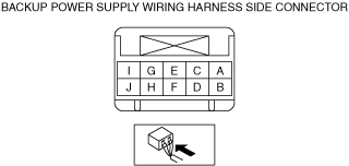
BACKUP POWER SUPPLY INSPECTION
id092100909200
1. Remove the following parts:
2. Verify that the voltages of each of the terminals are as indicated in the terminal voltage table (reference).
ac9wzw00005428
|
|
Terminal |
Signal name |
Connected to |
Test condition |
Voltage (V) |
Inspection item |
|
|---|---|---|---|---|---|---|
|
A
|
Power supply
|
Rear body control module (RBCM)
|
Under any condition
|
B+
|
• Rear body control module (RBCM)
• Related wiring harness
|
|
|
B
|
Power supply (IG1)
|
METER1 10 A fuse
|
Ignition switched ON (engine off or on)
|
B+
|
• METER1 10 A fuse
• Related wiring harness
|
|
|
Ignition switched OFF (LOCK)
|
1.0 or less
|
|||||
|
C
|
Power supply
|
D.LOCK 25 A fuse
|
Under any condition
|
B+
|
• D.LOCK 25 A fuse
• Related wiring harness
|
|
|
D
|
—
|
—
|
—
|
—
|
—
|
|
|
E
|
—
|
—
|
—
|
—
|
—
|
|
|
F
|
—
|
—
|
—
|
—
|
—
|
|
|
G
|
—
|
—
|
—
|
—
|
—
|
|
|
H
|
GND
|
Body ground
|
Under any condition
|
1.0 or less
|
• Body ground
• Related wiring harness
|
|
|
I
|
—
|
—
|
—
|
—
|
—
|
|
|
J
|
GND
|
Body ground
|
Under any condition
|
1.0 or less
|
• Body ground
• Related wiring harness
|
|