|
1
|
DETERMINE IF MALFUNCTION CAUSED BY ATX BODY
• Compare the malfunction symptom with the i-stop system stop condition.
• Is there any shock or slippage during acceleration with the i-stop system disabled?
|
Yes
|
Perform the applicable symptom troubleshooting procedure.
|
|
No
|
Go to the next step.
|
|
2
|
VERIFY DTC
• Retrieve the PCM, TCM, DSC HU/CM, SAS control module DTCs using the M-MDS.
• Are any DTCs present?
|
Yes
|
Go to the applicable DTC inspection.
|
|
No
|
Go to the next step.
|
|
3
|
DETERMINE IF MALFUNCTION CAUSE IS BRAKE FLUID PRESSURE SENSOR SIGNAL OR OTHER
• Put the vehicle in an i-stop condition (engine stopped).
• Monitor the PCM PID BFP using the M-MDS while the brake is depressed and held with the i-stop function operating.
• Does the monitoring value change?
|
Yes
|
Brake fluid pressure sensor (built-into DSC HU/CM) or DSC HU/CM brake pressure hold function malfunction.
• Replace the DSC HU/CM, then go to step 14.
|
|
No
|
Go to the next step.
|
|
4
|
INSPECT ELECTRIC AT OIL PUMP RELAY
• Switch the ignition off.
• Remove the electric AT oil pump relay.
• Inspect the electric AT oil pump relay.
• Is there any malfunction?
|
Yes
|
Replace the electric AT oil pump relay, then go to step 14.
|
|
No
|
Go to the next step.
|
|
5
|
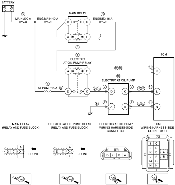
INSPECT ELECTRIC AT OIL PUMP RELAY POWER SUPPLY CIRCUIT FOR SHORT TO GROUND OR OPEN CIRCUIT
• Electric AT oil pump relay is removed.
• Measure the voltage at the electric AT oil pump relay terminal D (wiring harness-side).
• Is the voltage B+?
|
Yes
|
Go to the next step.
|
|
No
|
Inspect the MAIN 200 A fuse and AT PUMP 15 A fuse.
• If the fuse is blown:
-
? Refer to the wiring diagram and verify whether or not there is a common connector between MAIN 200 A fuse and electric AT oil pump relay terminal D.
If there is a common connector:
-
• Determine the malfunctioning part by inspecting the common connector and the terminal for corrosion, damage, or pin disconnection, and the common wiring harness for a short to ground.
• Repair or replace the malfunctioning part.
If there is no common connector:
-
• Repair or replace the wiring harness which has a short to ground.
• Replace the malfunctioning fuse.
• If the fuse is damaged:
-
? Replace the malfunctioning fuse.
• If all fuses are normal:
-
? Refer to the wiring diagram and verify whether or not there is a common connector between battery positive terminal and electric AT oil pump relay terminal D.
If there is a common connector:
-
• Determine the malfunctioning part by inspecting the common connector and the terminal for corrosion, damage, or pin disconnection, and the common wiring harness for an open circuit.
• Repair or replace the malfunctioning part.
If there is no common connector:
-
• Repair or replace the wiring harness which has an open circuit.
Go to step 14.
|
|
6
|
INSPECT ELECTRIC AT OIL PUMP RELAY POWER SUPPLY CIRCUIT FOR SHORT TO GROUND OR OPEN CIRCUIT
• Electric AT oil pump relay is removed.
• Switch the ignition ON (engine off).
• Measure the voltage at the electric AT oil pump relay terminal A (wiring harness-side).
• Is the voltage B+?
|
Yes
|
Go to the next step.
|
|
No
|
Inspect the ENGINE3 15 A fuse.
• If the fuse is blown:
-
? Refer to the wiring diagram and verify whether or not there is a common connector between ENGINE3 15 A fuse and electric AT oil pump relay terminal A.
If there is a common connector:
-
• Determine the malfunctioning part by inspecting the common connector and the terminal for corrosion, damage, or pin disconnection, and the common wiring harness for a short to ground.
• Repair or replace the malfunctioning part.
If there is no common connector:
-
• Repair or replace the wiring harness which has a short to ground.
• Replace the fuse.
• If the fuse is damaged:
-
? Replace the fuse.
• If the fuse is normal:
-
? Refer to the wiring diagram and verify whether or not there is a common connector between main relay terminal C and electric AT oil pump relay terminal A.
If there is a common connector:
-
• Determine the malfunctioning part by inspecting the common connector and the terminal for corrosion, damage, or pin disconnection, and the common wiring harness for an open circuit.
• Repair or replace the malfunctioning part.
If there is no common connector:
-
• Repair or replace the wiring harness which has an open circuit.
Go to step 14.
|
|
7
|
INSPECT ELECTRIC AT OIL PUMP CONNECTOR CONDITION
• Switch the ignition off.
• Disconnect the electric AT oil pump connector.
• Inspect for poor connection (such as damaged/pulled-out pins, corrosion).
• Is there any malfunction?
|
Yes
|
Repair or replace the connector and/or terminals, then go to step 14.
|
|
No
|
Go to the next step.
|
|
8
|
INSPECT ELECTRIC AT OIL PUMP GROUND CIRCUIT FOR OPEN CIRCUIT
• Electric AT oil pump relay is removed.
• Verify that the electric AT oil pump connector is disconnected.
• Inspect for continuity between electric AT oil pump terminal A (wiring harness-side) and body ground.
• Is there continuity?
|
Yes
|
Go to the next step.
|
|
No
|
Refer to the wiring diagram and verify whether or not there is a common connector between electric AT oil pump terminal A and body ground.
If there is a common connector:
• Determine the malfunctioning part by inspecting the common connector and the terminal for corrosion, damage, or pin disconnection, and the common wiring harness for an open circuit.
• Repair or replace the malfunctioning part.
If there is no common connector:
• Inspect for the following:
-
? Open circuit between electric AT oil pump and body ground
? Loose or lifting ground point
-
• Repair or replace the malfunctioning part.
Go to step 14.
|
|
9
|
INSPECT ELECTRIC AT OIL PUMP POWER SUPPLY CIRCUIT FOR SHORT TO GROUND
• Electric AT oil pump relay is removed.
• Verify that the electric AT oil pump connector is disconnected.
• Inspect for continuity between electric AT oil pump relay terminal C (wiring harness-side) and body ground.
• Is there continuity?
|
Yes
|
Refer to the wiring diagram and verify whether or not there is a common connector between electric AT oil pump relay terminal C and electric AT oil pump terminal D.
If there is a common connector:
• Determine the malfunctioning part by inspecting the common connector and the terminal for corrosion, damage, or pin disconnection, and the common wiring harness for a short to ground.
• Repair or replace the malfunctioning part.
If there is no common connector:
• Repair or replace the wiring harness which has a short to ground.
Go to step 14.
|
|
No
|
Go to the next step.
|
|
10
|
INSPECT ELECTRIC AT OIL PUMP POWER SUPPLY CIRCUIT FOR OPEN CIRCUIT
• Electric AT oil pump relay is removed.
• Verify that the electric AT oil pump connector is disconnected.
• Inspect for continuity between electric AT oil pump relay terminal C (wiring harness-side) and electric AT oil pump terminal D (wiring harness-side).
• Is there continuity?
|
Yes
|
Go to the next step.
|
|
No
|
Refer to the wiring diagram and verify whether or not there is a common connector between electric AT oil pump relay terminal C and electric AT oil pump terminal D.
If there is a common connector:
• Determine the malfunctioning part by inspecting the common connector and the terminal for corrosion, damage, or pin disconnection, and the common wiring harness for an open circuit.
• Repair or replace the malfunctioning part.
If there is no common connector:
• Repair or replace the wiring harness which has an open circuit.
Go to step 14.
|
|
11
|
INSPECT TCM CONNECTOR CONDITION
• Disconnect the TCM connector.
• Inspect for poor connection (such as damaged/pulled-out pins, corrosion).
• Is there any malfunction?
|
Yes
|
Repair or replace the connector and/or terminals, then go to step 14.
|
|
No
|
Go to the next step.
|
|
12
|
INSPECT TCM CIRCUIT FOR SHORT TO GROUND
• Electric AT oil pump relay is removed.
• Verify that the electric AT oil pump and TCM connectors are disconnected.
• Inspect for continuity between the following terminals (wiring harness-side) and body ground:
-
? Electric AT oil pump relay terminal E
? Electric AT oil pump terminal C
? Electric AT oil pump terminal B
• Is there continuity?
|
Yes
|
Refer to the wiring diagram and verify whether or not there is a common connector between the following terminals:
• Electric AT oil pump relay terminal E—TCM terminal K
• Electric AT oil pump terminal C—TCM terminal L
• Electric AT oil pump terminal B—TCM terminal N
If there is a common connector:
• Determine the malfunctioning part by inspecting the common connector and the terminal for corrosion, damage, or pin disconnection, and the common wiring harness for a short to ground.
• Repair or replace the malfunctioning part.
If there is no common connector:
• Repair or replace the wiring harness which has a short to ground.
Go to step 14.
|
|
No
|
Go to the next step.
|
|
13
|
INSPECT TCM CIRCUIT FOR OPEN CIRCUIT
• Electric AT oil pump relay is removed.
• Verify that the electric AT oil pump and TCM connectors are disconnected.
• Inspect for continuity between the following terminals (wiring harness-side):
-
? Electric AT oil pump relay terminal E—TCM terminal K
? Electric AT oil pump terminal C—TCM terminal L
? Electric AT oil pump terminal B—TCM terminal N
• Is there continuity?
|
Yes
|
Replace the electric AT oil pump, then go to the next step.
|
|
No
|
Refer to the wiring diagram and verify whether or not there is a common connector between the following terminals:
• Electric AT oil pump relay terminal E—TCM terminal K
• Electric AT oil pump terminal C—TCM terminal L
• Electric AT oil pump terminal B—TCM terminal N
If there is a common connector:
• Determine the malfunctioning part by inspecting the common connector and the terminal for corrosion, damage, or pin disconnection, and the common wiring harness for an open circuit.
• Repair or replace the malfunctioning part.
If there is no common connector:
• Repair or replace the wiring harness which has an open circuit.
Go to the next step.
|
|
14
|
Verify the test results.
• If normal, return to the diagnostic index to service any additional symptoms.
• If a malfunction remains, inspect the related Service Information and perform the repair or diagnosis.
-
? If the vehicle is repaired, troubleshooting is completed.
? If the vehicle is not repaired or additional diagnostic information is not available, replace the PCM.
|