|
1
|
VERIFY OTHER 360°VIEW MONITOR CONTROL MODULE DTCs
• Clear the DTC for the 360°view monitor control module using the M-MDS.
• Retrieve the 360°view monitor control module DTCs using the M-MDS.
• Is DTC U3000:41 or U3000:49 displayed?
|
Yes
|
Replace the 360°view monitor control module, then go to Step 19.
|
|
No
|
Go to the next step.
|
|
2
|
INSPECT 360°VIEW MONITOR CONTROL MODULE CONNECTOR CONDITION
• Switch the ignition off.
• Disconnect the negative battery terminal.
• Disconnect the 360°view monitor control module connector.
• Inspect the connector engagement and connection condition and inspect the terminals for damage, deformation, corrosion, or disconnection.
• Is the connector normal?
|
Yes
|
Go to the next step.
|
|
No
|
Repair or replace the connector, then go to Step 19.
|
|
3
|
INSPECT REAR MOUNT CAMERA CONNECTOR CONDITION
• Disconnect the rear mount camera connector.
• Inspect the connector engagement and connection condition and inspect the terminals for damage, deformation, corrosion, or disconnection.
• Is the connector normal?
|
Yes
|
Go to the next step.
|
|
No
|
Repair or replace the connector, then go to Step 19.
|
|
4
|
INSPECT REAR MOUNT CAMERA CIRCUIT FOR SHORT TO GROUND
• Verify that the rear mount camera and 360°view monitor control module connectors are disconnected.
• Inspect for continuity between the following terminals (wiring harness-side) and body ground:
-
? Rear mount camera terminal B
• Is there continuity?
|
Yes
|
Refer to the wiring diagram and verify whether or not there is a common connector between the following terminals:
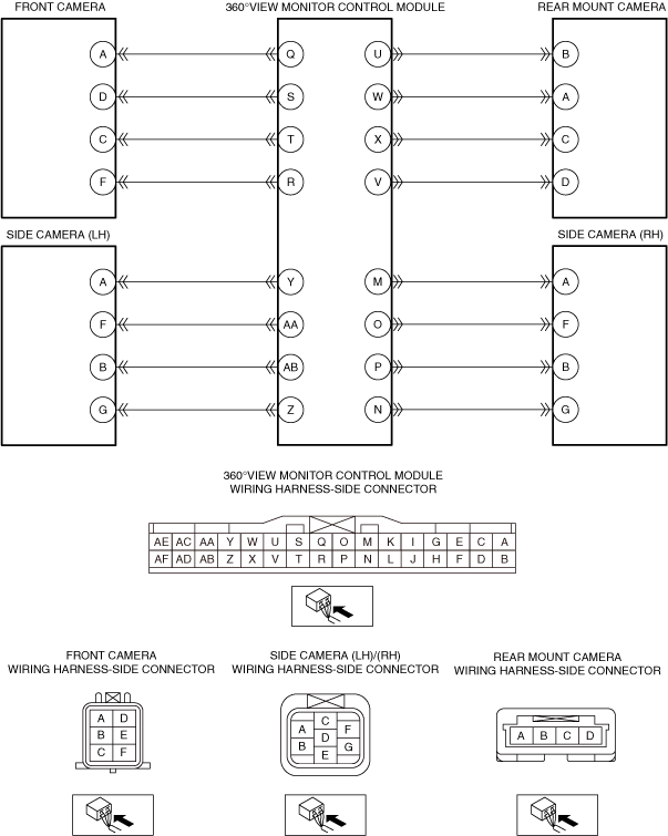
• 360°view monitor control module terminal U—Rear mount camera terminal B
If there is a common connector:
• Determine the malfunctioning part by inspecting the common connector and the terminal for corrosion, damage, or pin disconnection, and the common wiring harness for a short to ground.
• Repair or replace the malfunctioning part.
If there is no common connector:
• Repair or replace the wiring harness which has a short to ground.
Go to Step 19.
|
|
No
|
Go to the next step.
|
|
5
|
INSPECT REAR MOUNT CAMERA CIRCUIT FOR OPEN CIRCUIT
• Verify that the rear mount camera and 360°view monitor control module connectors are disconnected.
• Inspect for continuity between the following terminals (wiring harness-side):
-
? 360°view monitor control module terminal U—Rear mount camera terminal B
• Is there continuity?
|
Yes
|
Go to the next step.
|
|
No
|
Refer to the wiring diagram and verify whether or not there is a common connector between the following terminals:
• 360°view monitor control module terminal U—Rear mount camera terminal B
If there is a common connector:
• Determine the malfunctioning part by inspecting the common connector and the terminal for corrosion, damage, or pin disconnection, and the common wiring harness for an open circuit.
• Repair or replace the malfunctioning part.
If there is no common connector:
• Repair or replace the wiring harness which has an open circuit.
Go to Step 19.
|
|
6
|
INSPECT REAR MOUNT CAMERA
• Inspect the rear mount camera.
• Is the rear mount camera normal?
|
Yes
|
Go to the next step.
|
|
No
|
Replace the rear mount camera, then go to Step 19.
|
|
7
|
INSPECT SIDE CAMERA (LH) CONNECTOR CONDITION
• Disconnect the side camera (LH) connector.
• Inspect the connector engagement and connection condition and inspect the terminals for damage, deformation, corrosion, or disconnection.
• Is the connector normal?
|
Yes
|
Go to the next step.
|
|
No
|
Repair or replace the connector, then go to Step 19.
|
|
8
|
INSPECT SIDE CAMERA (LH) CIRCUIT FOR SHORT TO GROUND
• Verify that the side camera (LH) and 360°view monitor control module connectors are disconnected.
• Inspect for continuity between the following terminals (wiring harness-side) and body ground:
-
? Side camera (LH) terminal A
• Is there continuity?
|
Yes
|
Refer to the wiring diagram and verify whether or not there is a common connector between the following terminals:
• 360°view monitor control module terminal Y—Side camera (LH) terminal A
If there is a common connector:
• Determine the malfunctioning part by inspecting the common connector and the terminal for corrosion, damage, or pin disconnection, and the common wiring harness for a short to ground.
• Repair or replace the malfunctioning part.
If there is no common connector:
• Repair or replace the wiring harness which has a short to ground.
Go to Step 19.
|
|
No
|
Go to the next step.
|
|
9
|
INSPECT SIDE CAMERA (LH) CIRCUIT FOR OPEN CIRCUIT
• Verify that the side camera (LH) and 360°view monitor control module connectors are disconnected.
• Inspect for continuity between the following terminals (wiring harness-side):
-
? 360°view monitor control module terminal Y—Side camera (LH) terminal A
• Is there continuity?
|
Yes
|
Go to the next step.
|
|
No
|
Refer to the wiring diagram and verify whether or not there is a common connector between the following terminals:
• 360°view monitor control module terminal Y—Side camera (LH) terminal A
If there is a common connector:
• Determine the malfunctioning part by inspecting the common connector and the terminal for corrosion, damage, or pin disconnection, and the common wiring harness for an open circuit.
• Repair or replace the malfunctioning part.
If there is no common connector:
• Repair or replace the wiring harness which has an open circuit.
Go to Step 19.
|
|
10
|
INSPECT SIDE CAMERA (LH)
• Inspect the side camera (LH).
• Is the side camera (LH) normal?
|
Yes
|
Go to the next step.
|
|
No
|
Replace the side camera (LH), then go to Step 19.
|
|
11
|
INSPECT SIDE CAMERA (RH) CONNECTOR CONDITION
• Disconnect the side camera (RH) connector.
• Inspect the connector engagement and connection condition and inspect the terminals for damage, deformation, corrosion, or disconnection.
• Is the connector normal?
|
Yes
|
Go to the next step.
|
|
No
|
Repair or replace the connector, then go to Step 19.
|
|
12
|
INSPECT SIDE CAMERA (RH) CIRCUIT FOR SHORT TO GROUND
• Verify that the side camera (RH) and 360°view monitor control module connectors are disconnected.
• Inspect for continuity between the following terminals (wiring harness-side) and body ground:
-
? Side camera (RH) terminal A
• Is there continuity?
|
Yes
|
Refer to the wiring diagram and verify whether or not there is a common connector between the following terminals:
• 360°view monitor control module terminal M—Side camera (RH) terminal A
If there is a common connector:
• Determine the malfunctioning part by inspecting the common connector and the terminal for corrosion, damage, or pin disconnection, and the common wiring harness for a short to ground.
• Repair or replace the malfunctioning part.
If there is no common connector:
• Repair or replace the wiring harness which has a short to ground.
Go to Step 19.
|
|
No
|
Go to the next step.
|
|
13
|
INSPECT SIDE CAMERA (RH) CIRCUIT FOR OPEN CIRCUIT
• Verify that the side camera (RH) and 360°view monitor control module connectors are disconnected.
• Inspect for continuity between the following terminals (wiring harness-side):
-
? 360°view monitor control module terminal M—Side camera (RH) terminal A
• Is there continuity?
|
Yes
|
Go to the next step.
|
|
No
|
Refer to the wiring diagram and verify whether or not there is a common connector between the following terminals:
• 360°view monitor control module terminal M—Side camera (RH) terminal A
If there is a common connector:
• Determine the malfunctioning part by inspecting the common connector and the terminal for corrosion, damage, or pin disconnection, and the common wiring harness for an open circuit.
• Repair or replace the malfunctioning part.
If there is no common connector:
• Repair or replace the wiring harness which has an open circuit.
Go to Step 19.
|
|
14
|
INSPECT SIDE CAMERA (RH)
• Inspect the side camera (RH).
• Is the side camera (RH) normal?
|
Yes
|
Go to the next step.
|
|
No
|
Replace the side camera (RH), then go to Step 19.
|
|
15
|
INSPECT FRONT CAMERA CONNECTOR CONDITION
• Disconnect the front camera connector.
• Inspect the connector engagement and connection condition and inspect the terminals for damage, deformation, corrosion, or disconnection.
• Is the connector normal?
|
Yes
|
Go to the next step.
|
|
No
|
Repair or replace the connector, then go to Step 19.
|
|
16
|
INSPECT FRONT CAMERA CIRCUIT FOR SHORT TO GROUND
• Verify that the front camera and 360°view monitor control module connectors are disconnected.
• Inspect for continuity between the following terminals (wiring harness-side) and body ground:
-
? Front camera terminal A
• Is there continuity?
|
Yes
|
Refer to the wiring diagram and verify whether or not there is a common connector between the following terminals:
• 360°view monitor control module terminal Q—Front camera terminal A
If there is a common connector:
• Determine the malfunctioning part by inspecting the common connector and the terminal for corrosion, damage, or pin disconnection, and the common wiring harness for a short to ground.
• Repair or replace the malfunctioning part.
If there is no common connector:
• Repair or replace the wiring harness which has a short to ground.
Go to Step 19.
|
|
No
|
Go to the next step.
|
|
17
|
INSPECT FRONT CAMERA CIRCUIT FOR OPEN CIRCUIT
• Verify that the front camera and 360°view monitor control module connectors are disconnected.
• Inspect for continuity between the following terminals (wiring harness-side):
-
? 360°view monitor control module terminal Q—Front camera terminal A
• Is there continuity?
|
Yes
|
Go to the next step.
|
|
No
|
Refer to the wiring diagram and verify whether or not there is a common connector between the following terminals:
• 360°view monitor control module terminal Q—Front camera terminal A
If there is a common connector:
• Determine the malfunctioning part by inspecting the common connector and the terminal for corrosion, damage, or pin disconnection, and the common wiring harness for an open circuit.
• Repair or replace the malfunctioning part.
If there is no common connector:
• Repair or replace the wiring harness which has an open circuit.
Go to Step 19.
|
|
18
|
INSPECT FRONT CAMERA
• Inspect the front camera.
• Is the front camera normal?
|
Yes
|
Go to the next step.
|
|
No
|
Replace the front camera, then go to the next step.
|
|
19
|
VERIFY THAT REPAIRS HAVE BEEN COMPLETED
• Always reconnect all disconnected connectors.
• Connect the negative battery terminal.
• Clear the DTC for the 360°view monitor control module using the M-MDS.
• Retrieve the 360°view monitor control module DTCs using the M-MDS.
• Is the same Pending DTC present?
|
Yes
|
Repeat the inspection from Step 1.
• If the malfunction recurs, replace the 360°view monitor control module.
Go to the next step.
|
|
No
|
Go to the next step.
|
|
20
|
VERIFY IF OTHER DTCs DISPLAYED
• Are any other DTCs displayed?
|
Yes
|
Repair or replace the malfunctioning part according to the applicable DTC troubleshooting.
|
|
No
|
DTC troubleshooting completed.
|