am6xuw00006227
|
DTC P1450:00 [PCM (SKYACTIV-G 2.5T)]
id0102s8303100
Details On DTCs
|
DESCRIPTION |
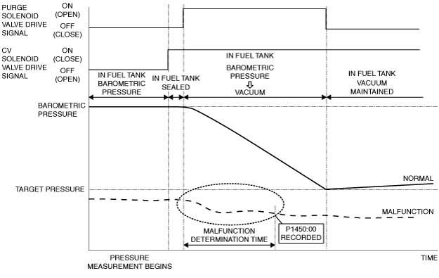
Evaporator system: abnormal negative pressure in fuel tank |
|
|---|---|---|
|
DETECTION CONDITION
|
Determination conditions
|
• Target negative pressure exceeding the specified time or more is generated from negative pressure inducted to the fuel tank by the operation of the purge solenoid valve after the fuel tank is sealed (CV solenoid valve ON).
|
|
Preconditions
|
• Period ignition is switched off before engine is started: 120 min or more
• Engine coolant temperature at engine start: 1.67—43.33 °C {35.1—109.9 °F}*1
• Time elapsed from engine start: 5.5—90 min
• Fuel level in fuel tank: 10—90 %*1
• Desired ambient air temperature: 4.4—43.3 °C {40—109 °F}*1
• Barometric pressure: 72.23 Pa {7.365 kgf/m2, 0.01048 psi} or more*1
• Charging efficiency: 3—65 %*1
• Vehicle speed: 64—144.8 km/h {40.00—89.97 mph}*1
• Purge flow amount: 15 l/min or more
*1: Standard can be verified by displaying PIDs using M-MDS
|
|
|
Malfunction determination period
|
• 75 s period
|
|
|
Drive cycle
|
• 2
|
|
|
Self test type
|
• CMDTC self test
|
|
|
Sensor used
|
• Fuel tank pressure sensor
|
|
|
FAIL-SAFE FUNCTION
|
• Not applicable
|
|
|
VEHICLE STATUS WHEN DTCs ARE OUTPUT
|
• Illuminates check engine light.
|
|
|
POSSIBLE CAUSE
|
• Fuel tank pressure sensor malfunction
• Restriction between charcoal canister and release-side passage
• Clogging between fuel tank and fuel tank pressure sensor
• Purge solenoid valve malfunction
• PCM malfunction
|
|
System Wiring Diagram
Function Explanation (DTC Detection Outline)
am6xuw00006227
|
Repeatability Verification Procedure
PID Item/Simulation Item Used In Diagnosis
PID/DATA monitor item table
|
Item |
Definition |
Unit |
Condition/Specification |
|---|---|---|---|
|
FTP
|
Fuel tank pressure
|
Pa {KPa}, mBar {Bar}, psi, in H20
|
• Displays fuel tank pressure
|
|
Fuel tank pressure sensor voltage
|
V
|
• Fuel tank pressure is equal to barometric pressure: Approx. 2.6 V
|
Simulation item table
|
Item |
Definition |
Unit |
Operation |
Other condition |
|---|---|---|---|---|
|
EVAPCP
|
Purge solenoid valve control signal
|
%
|
• Changes % and forcibly drives/stops purge solenoid valve.
|
• Under the following conditions:
|
|
EVAPCV
|
CV solenoid valve control signal
|
Off/On
|
• Selects Off/On to forcibly drive/stop the CV solenoid valve.
|
|
Function Inspection Using M-MDS
|
STEP |
INSPECTION |
RESULTS |
ACTION |
|---|---|---|---|
|
1
|
PURPOSE: VERIFY RELATED SERVICE INFORMATION AVAILABILITY
• Verify related Service Information availability.
• Is any related Service Information available?
|
Yes
|
Perform repair or diagnosis according to the available Service Information.
• If the vehicle is not repaired, go to the next step.
|
|
No
|
Go to the next step.
|
||
|
2
|
PURPOSE: RECORD FREEZE FRAME DATA/SNAPSHOT DATA AND DIAGNOSTIC MONITORING TEST RESULTS TO UTILIZE WITH REPEATABILITY VERIFICATION
• Record the FREEZE FRAME DATA/snapshot data and DIAGNOSTIC MONITORING TEST RESULTS (EVAP system related) on the repair order.
|
—
|
Go to the next step.
|
|
3
|
PURPOSE: INSPECTION OF CLOGGING BETWEEN FUEL TANK PRESSURE SENSOR AND FUEL TANK
• Perform the Pending Trouble Code Access Procedure and DTC Reading Procedure.
• Is the PENDING CODE/DTC P144A:00 also present?
|
Yes
|
The possibility of clogging between fuel tank pressure sensor and fuel tank is high.
• Go to the applicable PENDING CODE or DTC inspection.
|
|
No
|
Go to the next step.
|
||
|
4
|
PURPOSE: VERIFY FUEL TANK PRESSURE SENSOR MEASURED CORRECTLY
• Start the engine and idle it.
• Access the following simulation items using the M-MDS:
• Change to the following conditions using the simulation function.
• Access the FTP PID using the M-MDS.
• Does the negative pressure change when racing the engine?
|
Yes
|
Go to the next step.
|
|
No
|
Go to the troubleshooting procedure to perform the procedure from Step 1.
|
||
|
5
|
PURPOSE: VERIFY IF ATMOSPHERE BETWEEN CV SOLENOID VALVE AND ATMOSPHERE CAN RELEASE
• Access the following simulation items using the M-MDS:
• Change to the following conditions using the simulation function.
• Access the FTP PID using the M-MDS.
• Is the displayed PID value as follows?
|
Yes
|
Go to the next step.
|
|
No
|
Go to the troubleshooting procedure to perform the procedure from Step 2.
|
||
|
6
|
PURPOSE: VERIFY IF PURGE SOLENOID VALVE IS STUCK OPEN
• Access the following simulation items using the M-MDS:
• Change to the following conditions using the simulation function.
• Access the FTP PID using the M-MDS.
• Is the FTP PID value negative pressure?
|
Yes
|
Go to the troubleshooting procedure to perform the procedure from Step 5.
|
|
No
|
Go to the troubleshooting procedure to perform the procedure from Step 1.
|
Troubleshooting Diagnostic Procedure
|
STEP |
INSPECTION |
RESULTS |
ACTION |
|---|---|---|---|
|
1
|
PURPOSE: DETERMINE INTEGRITY OF FUEL TANK PRESSURE SENSOR
• Inspect the fuel tank pressure sensor.
• Is there any malfunction?
|
Yes
|
Replace the charcoal canister, then go to Step 6.
|
|
No
|
Go to the next step.
|
||
|
2
|
PURPOSE: DETERMINE INTEGRITY OF CV SOLENOID VALVE
• Inspect the CV solenoid valve.
• Is there any malfunction?
|
Yes
|
Replace the CV solenoid valve, then go to Step 6.
|
|
No
|
Go to the next step.
|
||
|
3
|
PURPOSE: VERIFY IF THERE IS RESTRICTION BETWEEN CHARCOAL CANISTER AND ATMOSPHERE RELEASE PASSAGE
• Verify the following passage hoses, pipe connection condition, and that there is no restriction.
• Is there any poor connection or restriction?
|
Yes
|
Repair or replace the malfunctioning part according to the inspection results, then go to Step 6.
|
|
No
|
Go to the next step.
|
||
|
4
|
PURPOSE: DETERMINE INTEGRITY OF CHARCOAL CANISTER
• Inspect the charcoal canister.
• Is there any malfunction?
|
Yes
|
Replace the charcoal canister, then go to Step 6.
|
|
No
|
Go to the next step.
|
||
|
5
|
PURPOSE: DETERMINE INTEGRITY OF PURGE SOLENOID VALVE
• Inspect the purge solenoid valve.
• Is there any malfunction?
|
Yes
|
Replace the purge solenoid valve, then go to the next step.
|
|
No
|
Go to the next step.
|
||
|
6
|
PURPOSE: VERIFICATION OF VEHICLE REPAIR COMPLETION
• Reconnect all the removed parts.
• Clear the DTC from the PCM memory using the M-MDS.
• Implement the repeatability verification procedure.
• Perform the Pending Trouble Code Access Procedure.
• Is the PENDING CODE for this DTC present?
|
Yes
|
Repeat the inspection from Step 1 of the troubleshooting diagnostic procedure.
• If the malfunction recurs, replace the PCM.
Go to the next step.
|
|
No
|
Go to the next step.
|
||
|
7
|
PURPOSE: VERIFY IF THERE IS ANY OTHER MALFUNCTION
• Is any other DTC or pending code stored?
|
Yes
|
Go to the applicable DTC inspection.
|
|
No
|
DTC troubleshooting completed.
|