|
1
|
VERIFY PCM, INSTRUMENT CLUSTER AND CLIMATE CONTROL UNIT DTC
• Retrieve the PCM, instrument cluster and climate control unit DTCs using the M-MDS.
• Are any DTCs present?
|
Yes
|
Go to the applicable DTC inspection.
|
|
No
|
Go to the next step.
|
|
2
|
DETERMINE IF MALFUNCTION CAUSE IS A/C RELAY CONTROL SIGNAL OR A/C REQUEST SIGNAL
• Access the PCM simulation item ACCS using the M-MDS.
• Start the engine and idle it.
• Turn the ACCS PID to ON from OFF using the M-MDS simulation function.
• Is the magnetic clutch engaged?
|
Yes
|
Go to the next step.
|
|
No
|
Go to Step 8.
|
|
3
|
DETERMINE IF MALFUNCTION CAUSE IS REFRIGERANT PRESSURE SENSOR OR OTHER
• Access the PCM PID AC_REQ using the M-MDS.
• Monitor the AC_REQ PID while turning on and off the air conditioner with switch on the control panel.
• Is the AC_REQ PID value normal?
|
Yes
|
Go to the next step.
|
|
No
|
Go to Step 5.
|
|
4
|
INSPECT REFRIGERANT PRESSURE SENSOR
• Inspect the refrigerant pressure sensor.
• Is there any malfunction?
|
Yes
|
Repair or replace the malfunctioning part according to the inspection results.
|
|
No
|
Inspect the following:
• Refrigerant charging amount
• A/C compressor seized
Repair or replace the malfunctioning part according to the inspection results if necessary.
|
|
5
|
DETERMINE IF MALFUNCTION CAUSE IS EVAPORATOR TEMPERATURE SENSOR OR OTHER
• Measure the voltage at the front climate control unit terminal 1P (Type A VIN/Type B VIN)/1E (Type C VIN) (wiring harness-side).
|
Yes
|
Go to Step 8.
|
|
No
|
Go to the next step.
|
|
6
|
INSPECT EVAPORATOR TEMPERATURE SENSOR
• Inspect the evaporator temperature sensor.
• Is there any malfunction?
|
Yes
|
Replace the evaporator temperature sensor.
|
|
No
|
Inspect for short or open circuit between the following terminals:
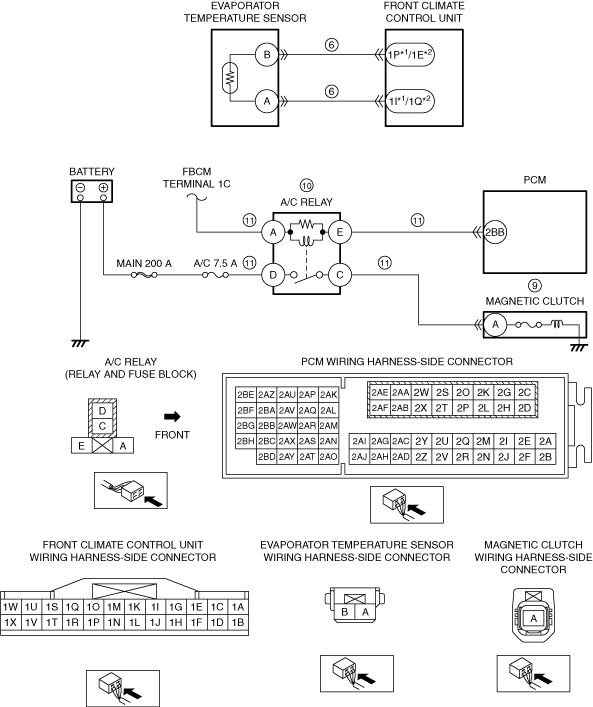
• Evaporator temperature sensor terminal B—Front climate control unit terminal 1P (Type A VIN/Type B VIN)/1E (Type C VIN)
• Evaporator temperature sensor terminal A—Front climate control unit terminal 1I (Type A VIN/Type B VIN)/1Q (Type C VIN)
If there is any malfunction:
-
? Refer to the wiring diagram and verify whether or not there is a common connector between the following terminals:
-
• Evaporator temperature sensor terminal B—Front climate control unit terminal 1P (Type A VIN/Type B VIN)/1E (Type C VIN)
• Evaporator temperature sensor terminal A—Front climate control unit terminal 1I (Type A VIN/Type B VIN)/1Q (Type C VIN)
If there is a common connector:
-
• Determine the malfunctioning part by inspecting the common connector and the terminal for corrosion, damage, or pin disconnection, and the common wiring harness for a short or open circuit.
• Repair or replace the malfunctioning part.
If there is no common connector:
-
• Repair or replace the wiring harness which has a short or open circuit.
|
|
7
|
DETERMINE IF MALFUNCTION CAUSE IS INSTRUMENT CLUSTER OR OTHER
• Verify the display indication of A/C system while turning on and off the air conditioner using the switch on the control panel.
• Does the display indicate properly?
|
Yes
|
A/C switch malfunction, or front climate control unit can not determine the A/C request or transmit the A/C request signal.
• Replace the front climate control unit.
|
|
No
|
Instrument cluster does not receive the A/C request signal from front climate control unit or transmit it to PCM.
• Replace the instrument cluster.
|
|
8
|
DETERMINE IF MALFUNCTION CAUSE IS A/C CONTROL SIGNAL OR MAGNETIC CLUTCH
• Start the engine and idle it.
• Access the PCM simulation item ACCS using the M-MDS.
• Turn the ACCS PID to ON from OFF using the M-MDS simulation function.
• Measure the voltage at the magnetic clutch terminal A (wiring harness-side).
• Is the voltage 10.5 V or more?
|
Yes
|
Go to the next step.
|
|
No
|
Go to Step 10.
|
|
9
|
INSPECT IF MALFUNCTION CAUSE IS MAGNETIC CLUTCH OR MAGNETIC CLUTCH GROUND CIRCUIT
• Switch the ignition off.
• Disconnect the magnetic clutch connector.
• Inspect for continuity between magnetic clutch terminal A (part-side) and body ground.
• Is there continuity?
|
Yes
|
Inspect the magnetic clutch.
Replace the magnetic clutch if necessary.
|
|
No
|
Inspect the A/C compressor. (poor contact to ground)
• If there is any malfunction:
-
? Repair or replace the malfunctioning part according to the inspection results.
• If there is no malfunction:
-
? Replace the A/C compressor. (internal circuit open)
|
|
10
|
INSPECT A/C RELAY
• Switch the ignition off.
• Remove the A/C relay.
• Is there any malfunction?
|
Yes
|
Replace the A/C relay.
|
|
No
|
Go to the next step.
|
|
11
|
INSPECT A/C RELAY CONTROL CIRCUIT FOR OPEN CIRCUIT
• A/C relay is removed.
• Disconnect the PCM connector.
• Inspect for continuity between A/C relay terminal E (wiring harness-side) and PCM terminal 2BB (wiring harness-side).
• Is there continuity?
|
Yes
|
Inspect for continuity between the following:
• Front body control module (FBCM) terminal 1C—A/C relay terminal A
• Battery positive terminal—A/C relay terminal D
• A/C relay terminal C—Magnetic clutch terminal A
Refer to the wiring diagram and verify whether or not there is a common connector between the following terminals:
• Front body control module (FBCM) terminal 1C—A/C relay terminal A
• Battery positive terminal—A/C relay terminal D
• A/C relay terminal C—Magnetic clutch terminal A
If there is a common connector:
• Determine the malfunctioning part by inspecting the common connector and the terminal for corrosion, damage, or pin disconnection, and the common wiring harness for an open circuit.
• Repair or replace the malfunctioning part.
If there is no common connector:
• Repair or replace the wiring harness which has an open circuit.
|
|
No
|
Refer to the wiring diagram and verify whether or not there is a common connector between A/C relay terminal E and PCM terminal 2BB.
If there is a common connector:
• Determine the malfunctioning part by inspecting the common connector and the terminal for corrosion, damage, or pin disconnection, and the common wiring harness for an open circuit.
• Repair or replace the malfunctioning part.
If there is no common connector:
• Repair or replace the wiring harness which has an open circuit.
|
|
12
|
Verify the test results.
• If normal, return to the diagnostic index to service any additional symptoms.
• If a malfunction remains, inspect the related Service Information and perform the repair or diagnosis.
-
? If the vehicle is repaired, troubleshooting is completed.
? If the vehicle is not repaired or additional diagnostic information is not available, replace the PCM.
|