Note
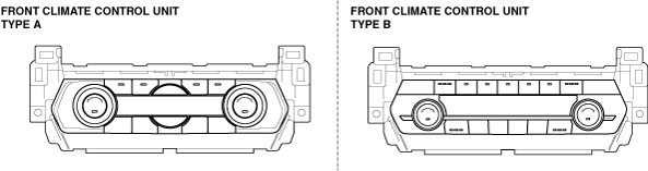
• There are two types of front climate control unit, type A and type B.
ac9wzw00005478
|
FRONT CLIMATE CONTROL UNIT INSPECTION
id074000805100
ac9wzw00005478
|
1. Disconnect the negative battery terminal. (See NEGATIVE BATTERY TERMINAL DISCONNECTION/CONNECTION.)
2. Remove the following parts:
3. Remove the front climate control unit with the connector connected. (See FRONT CLIMATE CONTROL UNIT REMOVAL/INSTALLATION.)
4. Connect the negative battery terminal. (See NEGATIVE BATTERY TERMINAL DISCONNECTION/CONNECTION.)
5. Switch the ignition ON (engine off or on).
6. Connect the negative (-) lead of the tester to body ground.
7. Insert the positive (+) lead of the tester into each front climate control unit terminal and measure the voltage according to the terminal voltage table.
ac9uuw00007359
|
Front Climate Control Unit Type A
Terminal voltage table (reference)
|
Terminal |
Signal name |
Connected to |
Measurement condition |
Voltage (V) |
Inspection item (s) |
|
|---|---|---|---|---|---|---|
|
1A
|
MS_CAN_H
|
CAN related module
|
Because this terminal is for communication, integrity determination by terminal voltage is not possible.
|
|||
|
1B
|
IG2
|
Front body control module (FBCM)
|
Switch the ignition ON (engine off or on)
|
B+
|
• Related wiring harness
• Front body control module (FBCM)
|
|
|
Switch the ignition off
|
1.0 or less
|
|||||
|
1C
|
MS_CAN_L
|
CAN related module
|
Because this terminal is for communication, integrity determination by terminal voltage is not possible.
|
|||
|
1D
|
—
|
—
|
—
|
—
|
—
|
|
|
1E
|
LIN
|
Rear climate control unit
|
Because this terminal is for communication, integrity determination by terminal voltage is not possible.
|
|||
|
1F
|
—
|
—
|
—
|
—
|
—
|
|
|
1G
|
GND
|
Body ground
|
Under any condition
|
1.0 or less
|
• Related wiring harness
|
|
|
1H
|
Blower fan speed control
|
Front blower motor
|
• Related wiring harness
• Front blower motor
|
|||
|
1I
|
Sensor GND
|
• Air intake actuator
• Driver-side front air mix actuator
• Passenger-side front air mix actuator
• Front airflow mode actuator
• Evaporator temperature sensor
• Cabin temperature sensor
|
Under any condition
|
1.0 or less
|
• Related wiring harness
• Front climate control unit: terminal voltage (1R)
|
|
|
1J
|
Solar radiation sensor (RH) input
|
Solar radiation sensor
|
Sunlight shined directly on solar radiation sensor
|
4
|
• Related wiring harness
• Front climate control unit: terminal voltage (1R)
• Solar radiation sensor
|
|
|
Blocking light to solar radiation sensor
|
1.0 or less
|
|||||
|
1K
|
—
|
—
|
—
|
—
|
—
|
|
|
1L
|
Solar radiation sensor (LH) input
|
Solar radiation sensor
|
Sunlight shined directly on solar radiation sensor
|
4
|
• Related wiring harness
• Front climate control unit: terminal voltage (1R)
• Solar radiation sensor
|
|
|
Blocking light to solar radiation sensor
|
1.0 or less
|
|||||
|
1M
|
Potentiometer input
|
• Passenger-side front air mix actuator (L.H.D.)
• Driver-side front air mix actuator (R.H.D.)
|
Set temperature at MAX HOT
|
4.2
|
• Related wiring harness
• Passenger-side front air mix actuator (L.H.D.)
• Driver-side front air mix actuator (R.H.D.)
• Front climate control unit: terminal voltage (1R)
|
|
|
Set temperature at MAX COLD
|
0.6
|
|||||
|
1N
|
Potentiometer input
|
Air intake actuator
|
Moving towards RECIRCULATE
|
3.8
|
• Related wiring harness
• Air intake actuator
• Front climate control unit: terminal voltage (1R)
|
|
|
Moving towards FRESH
|
1.4
|
|||||
|
1O
|
—
|
—
|
—
|
—
|
—
|
|
|
1P
|
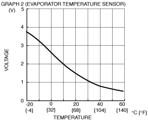
Evaporator temperature sensor input
|
Evaporator temperature sensor
|
Compared with temperature detected by evaporator temperature sensor
|
Refer to graph 2
|
• Related wiring harness
• Evaporator temperature sensor
• Front climate control unit: terminal voltage (1I)
|
|
|
1Q
|
—
|
—
|
—
|
—
|
—
|
|
|
1R
|
+5V
|
• Air intake actuator
• Driver-side front air mix actuator
• Passenger-side front air mix actuator
• Front airflow mode actuator
• Solar radiation sensor
|
Under any condition
|
5
|
• Related wiring harness
• Air intake actuator
• Driver-side front air mix actuator
• Passenger-side front air mix actuator
• Front airflow mode actuator
• Solar radiation sensor
• Front climate control unit: terminal voltage (1I)
|
|
|
1S
|
—
|
—
|
—
|
—
|
—
|
|
|
1T
|
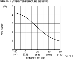
Cabin temperature sensor input
|
Cabin temperature sensor
|
Compared with temperature detected by cabin temperature sensor
|
Refer to graph 1
|
• Related wiring harness
• Cabin temperature sensor
• Front climate control unit: terminal voltage (1I)
|
|
|
1U
|
B+
|
• ROOM 25 A fuse
• INTERIOR 10A fuse
|
Under any condition
|
B+
|
• Related wiring harness
• ROOM 25 A fuse
• INTERIOR 10A fuse
|
|
|
1V
|
Potentiometer input
|
Front airflow mode actuator
|
VENT
|
0.8
|
• Related wiring harness
• Front airflow mode actuator
• Front climate control unit: terminal voltage (1R)
|
|
|
BI-LEVEL
|
1.4
|
|||||
|
HEAT
|
2.3
|
|||||
|
HEAT/DEF
|
2.9
|
|||||
|
DEFROSTER
|
3.8
|
|||||
|
1W
|
IG1
|
With i-stop
• IGNITION relay (IG1_STAB)
• METER2 15A fuse
Without i-stop
• C/U IG1 15 A fuse
|
Switch the ignition ON (engine off or on)
|
B+
|
• Related wiring harness
• C/U IG1 15 A fuse
|
|
|
Switch the ignition off
|
1.0 or less
|
|||||
|
1X
|
Potentiometer input
|
• Driver-side front air mix actuator (L.H.D.)
• Passenger-side front air mix actuator (R.H.D.)
|
Set temperature at MAX HOT
|
4.3
|
• Related wiring harness
• Driver-side front air mix actuator (L.H.D.)
• Passenger-side front air mix actuator (R.H.D.)
• Front climate control unit: terminal voltage (1R)
|
|
|
Set temperature at MAX COLD
|
0.6
|
|||||
|
2A
|
Motor operation (HOT)
|
• Passenger-side front air mix actuator (L.H.D.)
• Driver-side front air mix actuator (R.H.D.)
|
Moving towards HOT
|
B+
|
• Related wiring harness
• Passenger-side front air mix actuator (L.H.D.)
• Driver-side front air mix actuator (R.H.D.)
|
|
|
Moving towards COLD
|
1.0 or less
|
|||||
|
2B
|
Motor operation (FRESH)
|
Air intake actuator
|
Moving towards RECIRCULATE
|
1.0 or less
|
• Related wiring harness
• Air intake actuator
|
|
|
Moving towards FRESH
|
B+
|
|||||
|
2C
|
Motor operation (COLD)
|
• Passenger-side front air mix actuator (L.H.D.)
• Driver-side front air mix actuator (R.H.D.)
|
Moving towards HOT
|
1.0 or less
|
• Related wiring harness
• Passenger-side front air mix actuator (L.H.D.)
• Driver-side front air mix actuator (R.H.D.)
|
|
|
Moving towards COLD
|
B+
|
|||||
|
2D
|
Motor operation (RECIRCULATE)
|
Air intake actuator
|
Moving towards RECIRCULATE
|
B+
|
• Related wiring harness
• Air intake actuator
|
|
|
Moving towards FRESH
|
1.0 or less
|
|||||
|
2E
|
—
|
—
|
—
|
—
|
—
|
|
|
2F
|
Motor operation (HOT)
|
• Driver-side front air mix actuator (L.H.D.)
• Passenger-side front air mix actuator (R.H.D.)
|
Moving towards HOT
|
B+
|
• Related wiring harness
• Driver-side front air mix actuator (L.H.D.)
• Passenger-side front air mix actuator (R.H.D.)
|
|
|
Moving towards COLD
|
1.0 or less
|
|||||
|
2G
|
—
|
—
|
—
|
—
|
—
|
|
|
2H
|
Motor operation (COLD)
|
• Driver-side front air mix actuator (L.H.D.)
• Passenger-side front air mix actuator (R.H.D.)
|
Moving towards HOT
|
1.0 or less
|
• Related wiring harness
• Driver-side front air mix actuator (L.H.D.)
• Passenger-side front air mix actuator (R.H.D.)
|
|
|
Moving towards COLD
|
B+
|
|||||
|
2I
|
—
|
—
|
—
|
—
|
—
|
|
|
2J
|
Motor operation (DEFROSTER)
|
Front airflow mode actuator
|
Moving towards DEFROSTER
|
B+
|
• Related wiring harness
• Front airflow mode actuator
|
|
|
Moving towards VENT
|
1.0 or less
|
|||||
|
2K
|
—
|
—
|
—
|
—
|
—
|
|
|
2L
|
Motor operation (VENT)
|
Front airflow mode actuator
|
Moving towards VENT
|
B+
|
• Related wiring harness
• Front airflow mode actuator
|
|
|
Moving towards DEFROSTER
|
1.0 or less
|
|||||
 |
 |
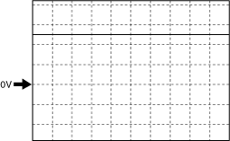
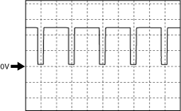
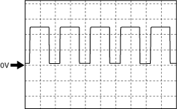
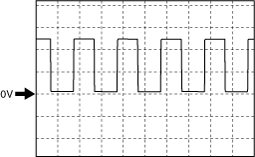
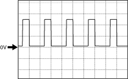
Blower fan speed control signal (Front climate control unit type A)
ac9uuw00009654
|
ac9uuw00009655
|
ac9uuw00009656
|
ac9uuw00009657
|
ac9uuw00009658
|
Front Climate Control Unit Type B
Terminal voltage table (reference)
|
Terminal |
Signal name |
Connected to |
Measurement condition |
Voltage (V) |
Inspection item (s) |
|
|---|---|---|---|---|---|---|
|
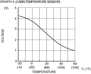
1A
|
Cabin temperature sensor input
|
Cabin temperature sensor
|
Compared with temperature detected by cabin temperature sensor
|
Refer to graph 3
|
• Related wiring harness
• Cabin temperature sensor
• Front climate control unit: terminal voltage (1Q)
|
|
|
1B
|
Potentiometer input
|
Front airflow mode actuator
|
VENT
|
0.8
|
• Related wiring harness
• Front airflow mode actuator
• Front climate control unit: terminal voltage (1C)
|
|
|
BI-LEVEL
|
1.4
|
|||||
|
HEAT
|
2.3
|
|||||
|
HEAT/DEF
|
2.9
|
|||||
|
DEFROSTER
|
3.8
|
|||||
|
1C
|
+5V
|
• Air intake actuator
• Driver-side front air mix actuator
• Passenger-side front air mix actuator
• Front airflow mode actuator
• Solar radiation sensor
|
Under any condition
|
5
|
• Related wiring harness
• Air intake actuator
• Driver-side front air mix actuator
• Passenger-side front air mix actuator
• Front airflow mode actuator
• Solar radiation sensor
• Front climate control unit: terminal voltage (1Q)
|
|
|
1D
|
Potentiometer input
|
Air intake actuator
|
Moving towards RECIRCULATE
|
3.8
|
• Related wiring harness
• Air intake actuator
• Front climate control unit: terminal voltage (1C)
|
|
|
Moving towards FRESH
|
1.4
|
|||||
|
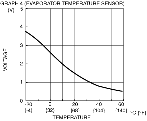
1E
|
Evaporator temperature sensor input
|
Evaporator temperature sensor
|
Compared with temperature detected by evaporator temperature sensor
|
Refer to graph 4
|
• Related wiring harness
• Evaporator temperature sensor
• Front climate control unit: terminal voltage (1Q)
|
|
|
1F
|
Solar radiation sensor (RH) input
|
Solar radiation sensor
|
Sunlight shined directly on solar radiation sensor
|
4
|
• Related wiring harness
• Front climate control unit: terminal voltage (1C)
• Solar radiation sensor
|
|
|
Blocking light to solar radiation sensor
|
1.0 or less
|
|||||
|
1G
|
—
|
—
|
—
|
—
|
—
|
|
|
1H
|
Solar radiation sensor (LH) input
|
Solar radiation sensor
|
Sunlight shined directly on solar radiation sensor
|
4
|
• Related wiring harness
• Front climate control unit: terminal voltage (1C)
• Solar radiation sensor
|
|
|
Blocking light to solar radiation sensor
|
1.0 or less
|
|||||
|
1I
|
GND
|
Body ground
|
Under any condition
|
1.0 or less
|
• Related wiring harness
|
|
|
1J
|
Motor operation (HOT)
|
• Driver-side front air mix actuator (L.H.D.)
• Passenger-side front air mix actuator (R.H.D.)
|
Moving towards HOT
|
B+
|
• Related wiring harness
• Driver-side front air mix actuator (L.H.D.)
• Passenger-side front air mix actuator (R.H.D.)
|
|
|
Moving towards COLD
|
1.0 or less
|
|||||
|
1K
|
MS_CAN_H
|
CAN related module
|
Because this terminal is for communication, integrity determination by terminal voltage is not possible.
|
|||
|
1L
|
Motor operation (COLD)
|
• Driver-side front air mix actuator (L.H.D.)
• Passenger-side front air mix actuator (R.H.D.)
|
Moving towards HOT
|
1.0 or less
|
• Related wiring harness
• Driver-side front air mix actuator (L.H.D.)
• Passenger-side front air mix actuator (R.H.D.)
|
|
|
Moving towards COLD
|
B+
|
|||||
|
1M
|
MS_CAN_L
|
CAN related module
|
Because this terminal is for communication, integrity determination by terminal voltage is not possible.
|
|||
|
1N
|
IG2
|
Front body control module (FBCM)
|
Switch the ignition ON (engine off or on)
|
B+
|
• Related wiring harness
• Front body control module (FBCM)
|
|
|
Switch the ignition off
|
1.0 or less
|
|||||
|
1O
|
LIN
|
Rear climate control unit
|
Because this terminal is for communication, integrity determination by terminal voltage is not possible.
|
|||
|
1P
|
—
|
—
|
—
|
—
|
—
|
|
|
1Q
|
Sensor GND
|
• Air intake actuator
• Driver-side front air mix actuator
• Passenger-side front air mix actuator
• Front airflow mode actuator
• Evaporator temperature sensor
• Cabin temperature sensor
|
Under any condition
|
1.0 or less
|
• Related wiring harness
• Front climate control unit: terminal voltage (1C)
|
|
|
1R
|
—
|
—
|
—
|
—
|
—
|
|
|
1S
|
—
|
—
|
—
|
—
|
—
|
|
|
1T
|
Blower fan speed control
|
Front blower motor
|
• Related wiring harness
• Front blower motor
|
|||
|
1U
|
B+
|
• ROOM 25 A fuse
• INTERIOR 10A fuse
|
Under any condition
|
B+
|
• Related wiring harness
• ROOM 25 A fuse
• INTERIOR 10A fuse
|
|
|
1V
|
—
|
—
|
—
|
—
|
—
|
|
|
1W
|
IG1
|
With i-stop
• IGNITION relay (IG1_STAB)
• METER2 15A fuse
Without i-stop
• C/U IG1 15 A fuse
|
Switch the ignition ON (engine off or on)
|
B+
|
• Related wiring harness
• C/U IG1 15 A fuse
|
|
|
Switch the ignition off
|
1.0 or less
|
|||||
|
1X
|
Front seat warmer switch signal
|
Because this terminal is for communication, determination using terminal voltage inspection is not possible
|
||||
|
2A
|
Motor operation (HOT)
|
• Passenger-side front air mix actuator (L.H.D.)
• Driver-side front air mix actuator (R.H.D.)
|
Moving towards HOT
|
B+
|
• Related wiring harness
• Passenger-side front air mix actuator (L.H.D.)
• Driver-side front air mix actuator (R.H.D.)
|
|
|
Moving towards COLD
|
1.0 or less
|
|||||
|
2B
|
Motor operation (DEFROSTER)
|
Front airflow mode actuator
|
Moving towards DEFROSTER
|
B+
|
• Related wiring harness
• Front airflow mode actuator
|
|
|
Moving towards VENT
|
1.0 or less
|
|||||
|
2C
|
Motor operation (COLD)
|
• Passenger-side front air mix actuator (L.H.D.)
• Driver-side front air mix actuator (R.H.D.)
|
Moving towards HOT
|
1.0 or less
|
• Related wiring harness
• Passenger-side front air mix actuator (L.H.D.)
• Driver-side front air mix actuator (R.H.D.)
|
|
|
Moving towards COLD
|
B+
|
|||||
|
2D
|
Motor operation (VENT)
|
Front airflow mode actuator
|
Moving towards VENT
|
B+
|
• Related wiring harness
• Front airflow mode actuator
|
|
|
Moving towards DEFROSTER
|
1.0 or less
|
|||||
|
2E
|
—
|
—
|
—
|
—
|
—
|
|
|
2F
|
Motor operation (RECIRCULATE)
|
Air intake actuator
|
Moving towards RECIRCULATE
|
B+
|
• Related wiring harness
• Air intake actuator
|
|
|
Moving towards FRESH
|
1.0 or less
|
|||||
|
2G
|
—
|
—
|
—
|
—
|
—
|
|
|
2H
|
Motor operation (FRESH)
|
Air intake actuator
|
Moving towards RECIRCULATE
|
1.0 or less
|
• Related wiring harness
• Air intake actuator
|
|
|
Moving towards FRESH
|
B+
|
|||||
|
2I
|
Potentiometer input
|
• Passenger-side front air mix actuator (L.H.D.)
• Driver-side front air mix actuator (R.H.D.)
|
Set temperature at MAX HOT
|
4.2
|
• Related wiring harness
• Passenger-side front air mix actuator (L.H.D.)
• Driver-side front air mix actuator (R.H.D.)
• Front climate control unit: terminal voltage (1C)
|
|
|
Set temperature at MAX COLD
|
0.6
|
|||||
|
2J
|
—
|
—
|
—
|
—
|
—
|
|
|
2K
|
Potentiometer input
|
• Driver-side front air mix actuator (L.H.D.)
• Passenger-side front air mix actuator (R.H.D.)
|
Set temperature at MAX HOT
|
4.3
|
• Related wiring harness
• Driver-side front air mix actuator (L.H.D.)
• Passenger-side front air mix actuator (R.H.D.)
• Front climate control unit: terminal voltage (1C)
|
|
|
Set temperature at MAX COLD
|
0.6
|
|||||
|
2L
|
—
|
—
|
—
|
—
|
—
|
|
 |
 |
Blower fan speed control signal (Front climate control unit type B)
ac9uuw00009654
|
ac9uuw00009655
|
ac9uuw00009656
|
ac9uuw00009657
|
ac9uuw00009658
|