 |
ac9uuw00006590
ENGINE MOUNT DISASSEMBLY/ASSEMBLY [SKYACTIV-G 2.5T]
id0110q8806900
No.1 Engine Mount (2WD)
1. Remove the front under cover No.2. (See FRONT UNDER COVER No.2 REMOVAL/INSTALLATION.)
2. Remove in the order indicated in the table.
3. Install in the reverse order of removal.
ac9uuw00006590
|
|
1
|
No.1 engine mount rubber
|
|
2
|
Bracket plate (No.1)
|
|
3
|
No.1 engine mount bracket
|
|
4
|
Bracket plate (No.2)
|
No.1 engine mount rubber removal note (2WD)
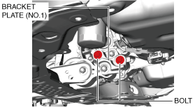
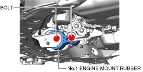
1. Loosen the bolts shown in the figure.
ac9uuw00006591
|
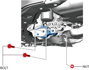
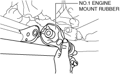
2. Remove the bolts shown in the figure.
ac9uuw00006592
|
3. Remove the No.1 engine mount rubber.
No.1 engine mount installation note (2WD)
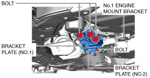
1. Install the No.1 engine mount bracket, bracket plate (No.1), and bracket plate (No.2) and temporarily tighten the installation bolts shown in the figure.
ac9uuw00006593
|
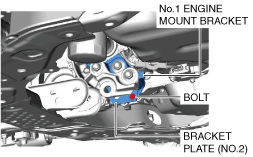
2. Tighten the bolt shown in the figure.
ac9uuw00006594
|
3. Install the No.1 engine mount rubber and temporarily tighten the installation bolts.
ac9wzw00005524
|
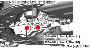
4. Tighten the No.1 engine mount bracket, bracket plate (No.1) and bracket plate (No.2) installation bolts in the order shown in the figure.
ac9uuw00006596
|
5. Tighten the No.1 engine mount rubber installation bolts.
ac9uuw00006597
|
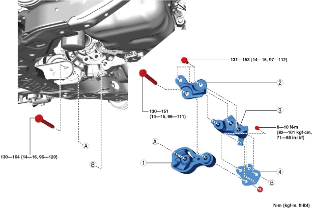
No.1 Engine Mount (4WD)
1. Remove the front under cover No.1 and front under cover No.2. (See FRONT UNDER COVER No.1 REMOVAL/INSTALLATION.) (See FRONT UNDER COVER No.2 REMOVAL/INSTALLATION.)
2. Remove the front splash shield. (See FRONT SPLASH SHIELD REMOVAL/INSTALLATION.)
3. Remove in the order indicated in the table.
4. Install in the reverse order of removal.
5. Inspect the front wheel alignment. (See FRONT WHEEL ALIGNMENT.)
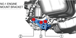
ac9uuw00006598
|
|
1
|
Bracket plate
|
|
2
|
No.1 engine mount rubber
|
|
3
|
No.1 engine mount bracket
|
No.1 engine mount rubber removal note (4WD)
1. Remove the joint bolt (steering gear side) and disconnect the steering shaft from the steering gear and linkage. (See STEERING WHEEL AND COLUMN REMOVAL/INSTALLATION.)
2. Remove the front crossmember extension from the front crossmember. (See FRONT CROSSMEMBER REMOVAL/INSTALLATION.)
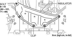
3. Remove the insulator shown in the figure.
ac9uuw00006599
|
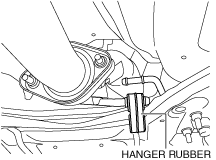
4. Remove the hanger rubber shown in the figure.
ac9uuw00006600
|
5. Disconnect the front stabilizer link (front stabilizer side). (See FRONT STABILIZER REMOVAL.) (See FRONT STABILIZER INSTALLATION.)
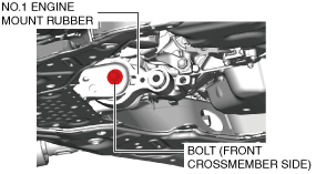
6. Remove the No.1 engine mount rubber installation bolt (front crossmember side).
ac9uuw00006601
|
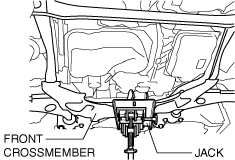
7. Support the front crossmember component using a jack.
ac9uuw00006602
|
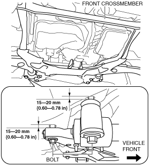
8. Loosen the front crossmember installation bolts (8) and lower the front crossmember component to 15—20 mm {0.60—0.78 in}.
ac9uuw00006603
|
9. Remove the No.1 engine mount rubber.
ac9uuw00006604
|
No.1 engine mount bracket removal note (4WD)
1. Remove the front crossmember component and No.1 engine mount rubber as a single unit. (See FRONT CROSSMEMBER REMOVAL/INSTALLATION.)
2. Remove the transfer. (See TRANSFER REMOVAL/INSTALLATION [GW6AX-EL].)
3. Remove the No.1 engine mount bracket.
No.1 engine mount bracket installation note (4WD)
1. Install the No.1 engine mount bracket and tighten the bolts in the order shown in the figure.
ac9uuw00006605
|
2. Install in the reverse order of removal.
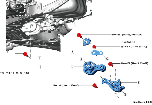
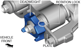
No.1 engine mount rubber, bracket plate installation note (4WD)
ac8wzw00002540
|
1. Install the No.1 engine mount rubber, bracket plate and deadweight to the front crossmember.
ac9uuw00006606
|
2. Tighten the front crossmember installation bolts. (See FRONT CROSSMEMBER REMOVAL/INSTALLATION.)
3. Remove the jack.
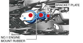
4. Tighten the No.1 engine mount rubber installation bolts.
ac9uuw00006607
|
5. Install in the reverse order of removal.
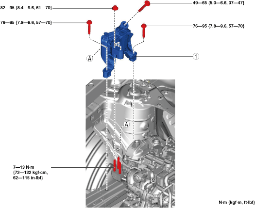
No.3 Engine Mount
1. Disconnect the negative battery terminal. (See NEGATIVE BATTERY TERMINAL DISCONNECTION/CONNECTION.)
2. Remove the plug hole plate. (See PLUG HOLE PLATE REMOVAL/INSTALLATION [SKYACTIV-G 2.5T].)
3. Remove in the order indicated in the table.
4. Install in the reverse order of removal.
ac9uuw00006608
|
|
1
|
No.3 engine mount
|
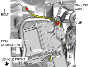
No.3 engine mount removal note
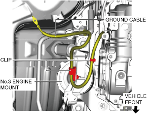
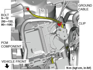
1. Remove the clip and bolt shown in the figure and set the ground cable aside.
ac9uuw00006609
|
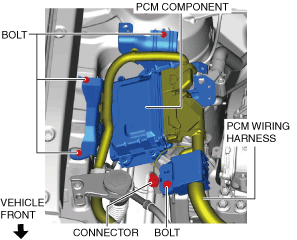
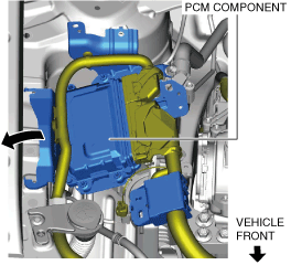
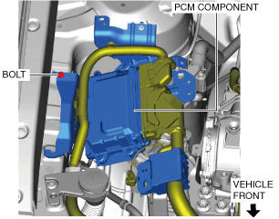
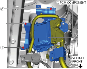
2. Set the PCM component aside using the following procedure:
ac9uuw00006610
|
ac9uuw00006611
|
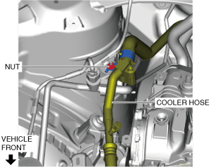
3. Remove the nut shown in the figure and set the cooler hose aside.
ac9wzw00005255
|
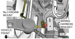
4. Disconnect the clip shown in the figure.
ac9uuw00006613
|
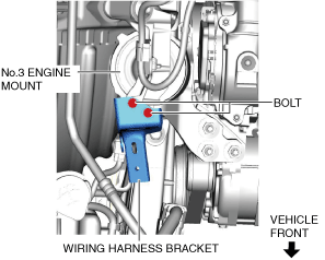
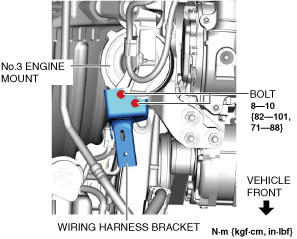
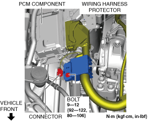
5. Remove the bolts shown in the figure and remove the wiring harness bracket.
ac9uuw00006614
|
6. Disconnect the ground cable clips shown in the figure.
ac9uuw00006615
|
7. Remove the front under cover No.2. (See FRONT UNDER COVER No.2 REMOVAL/INSTALLATION.)
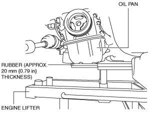
8. Before removing the No.3 engine mount, support the engine (oil pan) using a commercially available engine lifter or garage jack.
ac5wzw00006680
|
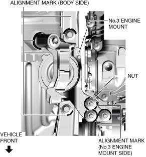
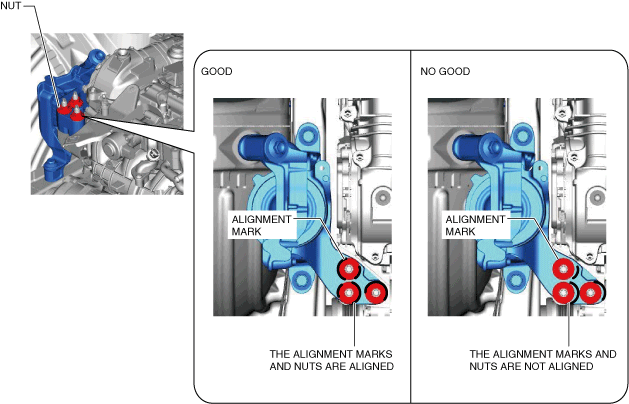
9. Place alignment marks on the locations shown in the figure so that they can be assembled to the same positions as before removal.
ac9uuw00006616
|
10. Remove the No.3 engine mount.
No.3 engine mount installation note
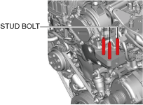
1. Tighten the engine front cover stud bolts.
ac9uuw00006617
|
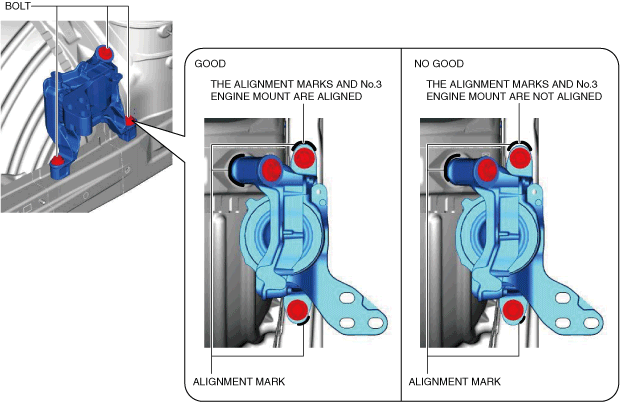
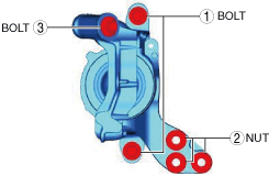
2. Temporarily tighten the No.3 engine mount installation bolts and nuts using the following procedure:
ac9uuw00006618
|
ac9uuw00006619
|
3. Tighten the No.3 engine mount installation bolts and nuts in the order shown in the figure.
ac9uuw00006620
|
Tightening torque
|
No. |
Tightening torque |
|---|---|
|
1
|
76—95 N·m {7.8—9.6 kgf·m, 57—70 ft·lbf}
|
|
2
|
82—95 N·m {8.4—9.6 kgf·m, 61—70 ft·lbf}
|
|
3
|
49—65 N·m {5.0—6.6 kgf·m, 37—47 ft·lbf}
|
4. Remove the engine lifter or garage jack.
5. Connect the ground cable clips shown in the figure.
ac9uuw00006615
|
6. Install the wiring harness bracket shown in the figure.
ac9uuw00006621
|
7. Connect the clip shown in the figure.
ac9uuw00006613
|
8. Return the cooler hose that was set aside to its original position and tighten the nut.
ac9wzw00005256
|
9. Install the PCM component using the following procedure:
ac9uuw00006623
|
ac9uuw00006624
|
ac9uuw00007429
|
10. Install the ground cable shown in the figure.
ac9uuw00006626
|
No.4 Engine Mount
1. Disconnect the negative battery terminal. (See NEGATIVE BATTERY TERMINAL DISCONNECTION/CONNECTION.)
2. Remove the air cleaner, air hose and fresh air duct as a single unit. (See INTAKE-AIR SYSTEM REMOVAL/INSTALLATION [SKYACTIV-G 2.5T].)
3. Remove the battery and battery tray. (See BATTERY REMOVAL/INSTALLATION.)
4. Remove in the order indicated in the table.
5. Install in the reverse order of removal.
ac9uuw00006627
|
|
1
|
No.4 engine mount rubber
|
|
2
|
No.4 engine mount bracket
|
No.4 engine mount rubber removal note
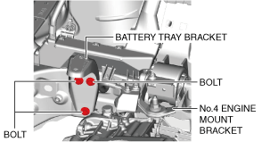
1. Loosen the battery tray bracket installation bolts.
ac9uuw00006628
|
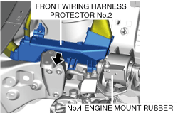
2. Set the front wiring harness protector No.2 aside from the body. (See RELAY AND FUSE BLOCK REMOVAL/INSTALLATION.)
ac9uuw00006629
|
3. Remove the front under cover No.2. (See FRONT UNDER COVER No.2 REMOVAL/INSTALLATION.)
ac5uuw00000662
|
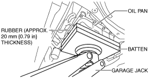
4. Before removing the No.4 engine mount rubber, support the transaxle using a commercially available engine lifter or garage jack.
5. Remove the No.4 engine mount rubber.
No.4 engine mount bracket removal note
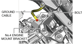
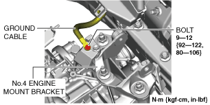
1. Remove the bolt shown in the figure and set the ground cable aside.
ac9uuw00006630
|
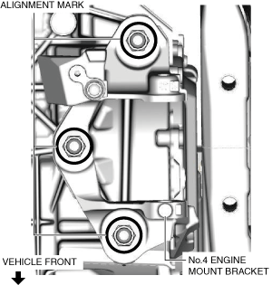
2. Place alignment marks on the locations shown in the figure so that they can be assembled to the same positions as before removal.
ac9uuw00006631
|
3. Remove the No.4 engine mount bracket.
No.4 engine mount bracket installation note
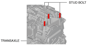
1. Tighten the transaxle stud bolts.
ac3wzw00000647
|
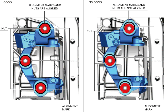
2. Align the alignment marks on the No.4 engine mount bracket and nuts, and temporarily tighten the nuts shown in the figure.
ac9uuw00006632
|
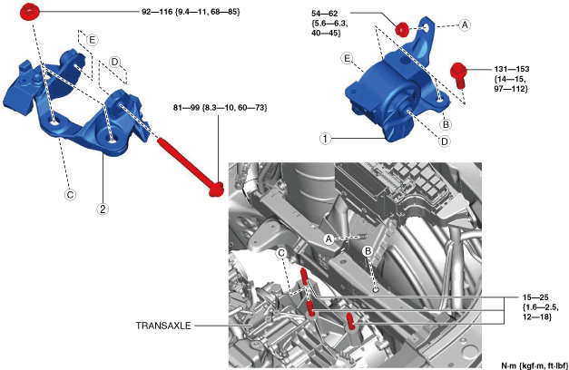
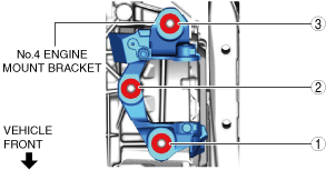
3. Tighten the No.4 engine mount bracket installation nuts in the order shown in the figure.
ac9uuw00006633
|
4. Install the ground cable to the No.4 engine mount bracket.
ac9uuw00006634
|
No.4 engine mount rubber installation note
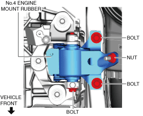
1. Install the No.4 engine mount rubber and temporarily tighten the bolts and nut shown in the figure.
ac9uuw00006635
|
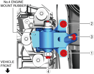
2. Tighten the No.4 engine mount rubber installation bolts and nut in the order shown in the figure.
ac9uuw00006636
|
Tightening torque
|
No. |
Tightening torque |
|---|---|
|
1, 2
|
131—153 N·m {14—15 kgf·m, 97—112 ft·lbf}
|
|
3
|
54—62 N·m {5.6—6.3 kgf·m, 40—45 ft·lbf}
|
|
4
|
81—99 N·m {8.3—10 kgf·m, 60—73 ft·lbf}
|
3. Remove the engine lifter or garage jack.
4. Install the front under cover No.2. (See FRONT UNDER COVER No.2 REMOVAL/INSTALLATION.)
5. Install the front wiring harness protector No.2. (See RELAY AND FUSE BLOCK REMOVAL/INSTALLATION.)
ac9uuw00006637
|
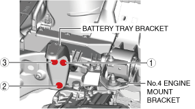
6. Tighten the battery tray bracket installation bolts in the order shown in the figure.
ac9uuw00006638
|