|
1
|
VERIFY PCM DTCs
• Retrieve the PCM DTCs using the M-MDS.
• Are any DTCs displayed?
|
Yes
|
Repair or replace the malfunctioning part according to the applicable DTC troubleshooting.
|
|
No
|
Go to the next step.
|
|
2
|
INSPECT AUDIO AMPLIFIER CONNECTOR CONDITION
• Switch the ignition off.
• Disconnect the negative battery terminal.
• Disconnect the audio amplifier connector.
• Inspect the connector engagement and connection condition and inspect the terminals for damage, deformation, corrosion, or disconnection.
• Is the connector normal?
|
Yes
|
Go to the next step.
|
|
No
|
Repair or replace the connector, then go to Step 6.
|
|
3
|
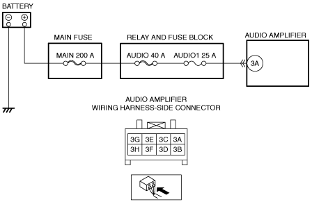
VERIFY AUDIO AMPLIFIER POWER SUPPLY VOLTAGE
• Verify that the audio amplifier connector is disconnected.
• Connect the negative battery terminal.
• Switch the ignition ON (engine off or on).
• Measure the voltage at the audio amplifier terminal 3A (wiring harness side).
• Is the voltage B+?
|
Yes
|
Go to the next step.
|
|
No
|
Inspect the AUDIO1 25 A fuse.
• If the fuse is blown:
-
? Refer to the wiring diagram and verify whether or not there is a common connector between AUDIO1 25 A fuse and audio amplifier terminal 3A.
If there is a common connector:
-
• Inspect the common connector and terminals for corrosion, damage, or disconnection and the common wiring harnesses for short to ground to determine the malfunctioning location.
• Repair or replace the malfunctioning location.
If there is no common connector:
-
• Repair or replace the wiring harness which is shorted to ground.
• Replace the fuse.
• If the fuse is damaged:
-
? Replace the fuse.
• If the fuse is normal:
-
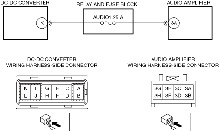
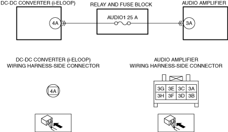
? Refer to the wiring diagram and verify whether or not there is a common connector between DC-DC converter terminal K and audio amplifier terminal 3A.
If there is a common connector:
-
• Inspect the common connector and terminals for corrosion, damage, or disconnection and the common wiring harnesses for an open circuit to determine the malfunctioning location.
• Repair or replace the malfunctioning location.
If there is no common connector:
-
• Repair or replace the wiring harness which has an open circuit.
|
|
4
|
INSPECT DC-DC CONVERTER CONNECTOR CONDITION
• Switch the ignition off.
• Disconnect the negative battery terminal.
• Disconnect the DC-DC converter connector.
• Inspect the connector engagement and connection condition and inspect the terminals for damage, deformation, corrosion, or disconnection.
• Is the connector normal?
|
Yes
|
Go to the next step.
|
|
No
|
Repair or replace the connector, then go to Step 6.
|
|
5
|
INSPECT DC-DC CONVERTER
• Inspect the DC-DC converter.
• Is there any malfunctioning part?
|
Yes
|
Repair or replace the DC-DC converter and go to the next step.
|
|
No
|
Go to the next step.
|
|
6
|
VERIFY THAT REPAIRS HAVE BEEN COMPLETED
• Always reconnect all disconnected connectors.
• Connect the negative battery terminal.
• Clear the DTC for the audio amplifier using the M-MDS.
• Switch the ignition ON (engine off or on) and wait for 5 s or more.
• Retrieve the audio amplifier DTCs using the M-MDS.
• Is the same DTC displayed?
|
Yes
|
Repeat the inspection from Step 1.
• If the malfunction recurs, replace the audio amplifier.
Go to the next step.
|
|
No
|
Go to the next step.
|
|
7
|
VERIFY IF OTHER DTCs DISPLAYED
• Are any other DTCs displayed?
|
Yes
|
Repair or replace the malfunctioning part according to the applicable DTC troubleshooting.
|
|
No
|
DTC troubleshooting completed.
|