System malfunction location
• U3003:16: SAS control module power supply voltage decreases (9 V or less)
• U3003:17: SAS control module power supply voltage increases (18 V or more)
Detection condition
-
Warning
-
• Detection conditions are for understanding the DTC outline before performing an inspection. Performing an inspection according to only the detection conditions may cause injury due to an operating error, or damage the system. When performing an inspection, always follow the inspection procedure.
• SAS control module power supply voltage is other than 9.1–17.9 V
Fail-safe
Not applicable
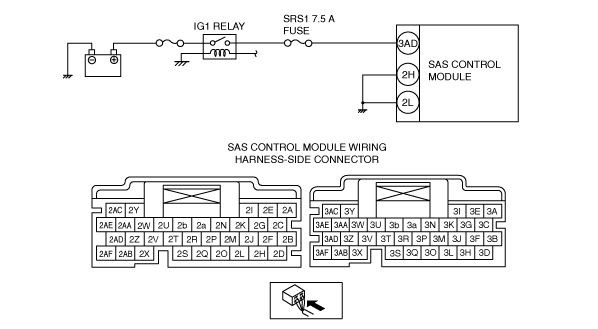
Possible cause
• Battery malfunction
• SRS1 7.5 A fuse malfunction
• Open circuit or short to body ground in wiring harness between IG1 relay and SAS control module
• Open circuit in the wiring harness between the SAS control module and body ground
• SAS control module malfunction