 |
am6xuw00010959
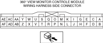
360°VIEW MONITOR CONTROL MODULE INSPECTION
id152000009500
1. Disconnect the negative battery terminal. (See NEGATIVE BATTERY TERMINAL DISCONNECTION/CONNECTION.)
2. Remove the following parts.
3. Partially peel back the floor covering.
4. Remove the foot support. (See FOOT SUPPORT REMOVAL/INSTALLATION.)
5. Remove the nuts and cover. (See 360°VIEW MONITOR CONTROL MODULE REMOVAL/INSTALLATION.)
6. Connect the negative battery terminal. (See NEGATIVE BATTERY TERMINAL DISCONNECTION/CONNECTION.)
7. Verify that the voltages of each of the terminals are as indicated in the terminal voltage table (reference).
am6xuw00010959
|
|
Terminal |
Signal name |
Connected to |
Test condition |
Voltage (V) |
Inspection item |
|
|---|---|---|---|---|---|---|
|
A
|
Power supply
|
INTERIOR2 10 A fuse
|
Under any condition
|
B+
|
• INTERIOR2 10 A fuse
• Related wiring harness
|
|
|
B
|
—
|
—
|
—
|
—
|
—
|
|
|
C
|
ACC relay control
|
ACC relay
|
Ignition switched ON or ACC (engine off)
|
B+
|
• ACC relay
• Related wiring harness
|
|
|
Ignition switched OFF (LOCK)
|
1.0 or less
|
|||||
|
D
|
—
|
—
|
—
|
—
|
—
|
|
|
E
|
Retract/return signal
|
Power outer mirror switch
|
Retract/return switch OFF
|
1.0 or less
|
• Power outer mirror switch
• Related wiring harness
|
|
|
Retract/return switch ON
|
B+
|
|||||
|
F
|
—
|
—
|
—
|
—
|
—
|
|
|
G
|
—
|
—
|
—
|
—
|
—
|
|
|
H
|
GND
|
Body ground
|
Under any condition
|
1.0 or less
|
• Body ground
• Related wiring harness
|
|
|
I
|
Monitor signal
|
Connectivity master unit (CMU)
|
Under any condition
|
1.0 or less
|
• 360°view monitor control
• Instrument cluster
• Related wiring harness
|
|
|
J
|
—
|
—
|
—
|
—
|
—
|
|
|
K
|
Monitor GND
|
Connectivity master unit (CMU)
|
Under any condition
|
1.0 or less
|
• 360°view monitor control
|
|
|
L
|
Shield ground
|
Body ground
|
Under any condition
|
1.0 or less
|
• 360°view monitor control
|
|
|
M
|
Side camera power supply
|
Side camera (RH)
|
Under any condition
|
Approx. 6
|
• Side camera (RH)
• 360°view monitor control
• Instrument cluster
• Related wiring harness
|
|
|
N
|
Side camera GND
|
Side camera (RH)
|
Under any condition
|
1.0 or less
|
• 360°view monitor control
|
|
|
O
|
Side camera signal
|
Side camera (RH)
|
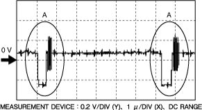
Wave pattern (See Inspection Using an Oscilloscope (Reference).)
|
• Side camera (RH)
• 360°view monitor control
• Related wiring harness
|
||
|
P
|
Side camera GND
|
Side camera (RH)
|
Under any condition
|
1.0 or less
|
• 360°view monitor control
|
|
|
Q
|
Front camera power supply
|
Front camera
|
Under any condition
|
Approx. 6
|
• Front camera
• 360°view monitor control
• Instrument cluster
• Related wiring harness
|
|
|
R
|
Front camera GND
|
Front camera
|
Under any condition
|
1.0 or less
|
• 360°view monitor control
|
|
|
S
|
Front camera signal
|
Front camera
|
Wave pattern (See Inspection Using an Oscilloscope (Reference).)
|
• Front camera
• 360°view monitor control
• Related wiring harness
|
||
|
T
|
Front camera GND
|
Front camera
|
Under any condition
|
1.0 or less
|
• 360°view monitor control
|
|
|
U
|
Rear mount camera power supply
|
Rear mount camera
|
Under any condition
|
Approx. 6
|
• Rear mount camera
• 360°view monitor control
• Instrument cluster
• Related wiring harness
|
|
|
V
|
Rear mount camera GND
|
Rear mount camera
|
Under any condition
|
1.0 or less
|
• 360°view monitor control
|
|
|
W
|
Rear mount camera signal
|
Rear mount camera
|
Wave pattern (See Inspection Using an Oscilloscope (Reference).)
|
• Rear mount camera
• 360°view monitor control
• Related wiring harness
|
||
|
X
|
Rear mount camera GND
|
Rear mount camera
|
Under any condition
|
1.0 or less
|
• 360°view monitor control
|
|
|
Y
|
Side camera power supply
|
Side camera (LH)
|
Under any condition
|
Approx. 6
|
• Side camera (LH)
• 360°view monitor control
• Instrument cluster
• Related wiring harness
|
|
|
Z
|
Side camera GND
|
Side camera (LH)
|
Under any condition
|
1.0 or less
|
• 360°view monitor control
|
|
|
AA
|
Side camera signal
|
Side camera (LH)
|
Wave pattern (See Inspection Using an Oscilloscope (Reference).)
|
• Side camera (LH)
• 360°view monitor control
• Related wiring harness
|
||
|
AB
|
Side camera GND
|
Side camera (LH)
|
Under any condition
|
1.0 or less
|
• 360°view monitor control
|
|
|
AC
|
—
|
—
|
—
|
—
|
—
|
|
|
AD
|
—
|
—
|
—
|
—
|
—
|
|
|
AE
|
CAN_H
|
CAN system related module
|
Terminal used for communication therefore determination based on terminal voltage is not possible.
|
|||
|
AF
|
CAN_L
|
CAN system related module
|
Terminal used for communication therefore determination based on terminal voltage is not possible.
|
|||
Inspection Using an Oscilloscope (Reference)
ac5wzw00009889
|