REAR DIFFERENTIAL REMOVAL/INSTALLATION
id031400800400
-
Caution
-
• Performing the following procedures could cause an open circuit in the rear ABS wheel-speed sensor wiring harness if it is pulled by mistake. Before servicing, disconnect the rear ABS wheel-speed sensor and set it aside so that the wiring harness will not be pulled by mistake.
• If the characteristic value of a new coupling component is not input to the 4WD control module or the characteristic value is input incorrectly after replacing the coupling component, it could result in the following conditions:
-
? The system does not operate normally.
? A problem with durability of the coupling component occurs.
-
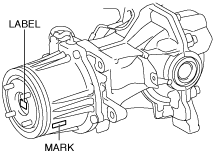
• Read out the characteristic value of the coupling component from the label or mark shown in the figure.
-
Note
-
• The 4WD control module stores the characteristic value of the coupling component before replacement.
• If the characteristic value of a new coupling component is not written, the 4WD control module does not store the value.
1. Switch the ignition ON (engine off).
2. Release the electric parking brake.
3. Switch the ignition off.
4. Disconnect the negative battery terminal. (See NEGATIVE BATTERY TERMINAL DISCONNECTION/CONNECTION.)
5. Remove the wheels and tires. (See WHEEL AND TIRE REMOVAL/INSTALLATION.)
6. Drain the rear differential oil into a container. (See DIFFERENTIAL OIL REPLACEMENT.)
7. Remove the following parts:
- (1) Floor under cover No.2 (See FLOOR UNDER COVER REMOVAL/INSTALLATION.)
-
- (2) Floor under cover No.1 (See FLOOR UNDER COVER REMOVAL/INSTALLATION.)
-
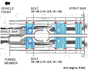
- (3) Brace bar
-
- (4) Tunnel member
-
- (5) Strut bar
-
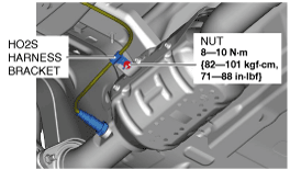
- (6) HO2S harness bracket
-
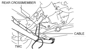
8. Remove the TWC from the mount rubber.
9. Disconnect the TWC from the main silencer. (See EXHAUST SYSTEM REMOVAL/INSTALLATION [SKYACTIV-G 2.5T].)
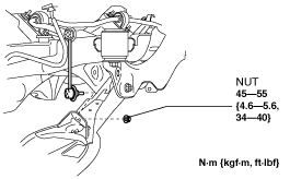
10. Suspend the TWC using a cable as shown in the figure.
11. Remove the propeller shaft. (See PROPELLER SHAFT REMOVAL/INSTALLATION.)
12. Disconnect the rear auto leveling sensor link. (With auto leveling sensor)
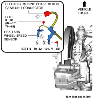
13. Disconnect the rear ABS wheel-speed sensor wiring harness and the electric parking brake motor gear unit connector and set it aside so that it does not interfere with the servicing.
14. Remove the wheel hub component. (See WHEEL HUB COMPONENT REMOVAL/INSTALLATION [4WD].)
15. Remove the dust cover. (See WHEEL HUB COMPONENT REMOVAL/INSTALLATION [4WD].)
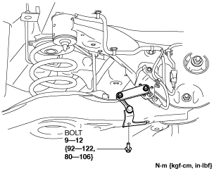
16. Disconnect the rear stabilizer control link from the rear lower arm.
17. Disconnect the rear trailing link from the hub support. (See REAR TRAILING LINK REMOVAL/INSTALLATION.)
18. Remove the rear coil spring. (See REAR COIL SPRING REMOVAL/INSTALLATION.)
19. Disconnect the rear shock absorber from the hub support. (See REAR SHOCK ABSORBER REMOVAL/INSTALLATION.)
20. Disconnect the rear lateral link from the hub support. (See REAR LATERAL LINK REMOVAL/INSTALLATION.)
21. Disconnect the rear upper arm from the hub support. (See REAR UPPER ARM REMOVAL/INSTALLATION [4WD].)
22. Remove the hub support. (See WHEEL HUB COMPONENT REMOVAL/INSTALLATION [4WD].)
23. Remove the rear drive shaft. (See REAR DRIVE SHAFT REMOVAL/INSTALLATION.)
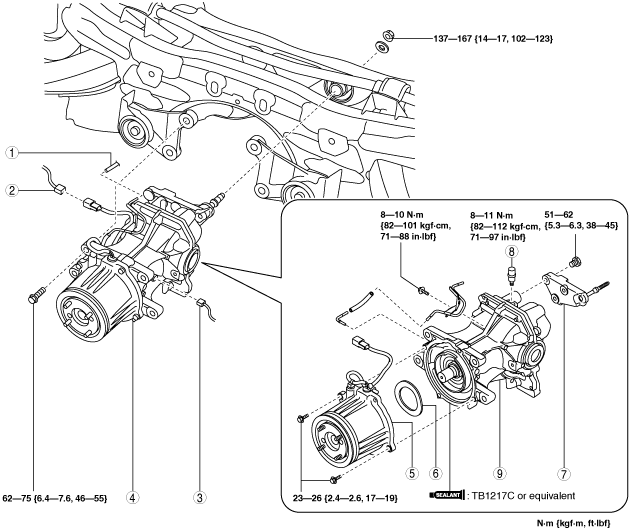
24. Remove in the order indicated in the table.
25. Install in the reverse order of removal. (See Suspension Links Installation Note.)
26. Add the specified rear differential oil. (See DIFFERENTIAL OIL REPLACEMENT.)
27. Perform the headlight auto leveling system initial setting. (With auto leveling sensor) (See HEADLIGHT AUTO LEVELING SYSTEM INITIALIZATION.)
|
1
|
Hose
|
|
2
|
Connector (4WD solenoid)
|
|
3
|
Connector (differential oil temperature sensor)
|
|
4
|
Rear differential component
|
|
5
|
Coupling component
|
|
6
|
Washer
|
|
7
|
Rear differential mounting bracket
|
|
8
|
Breather
|
|
9
|
Rear differential
|
Rear Differential Component Removal Note
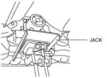
1. Support the rear differential using a jack.
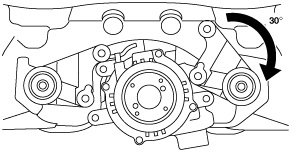
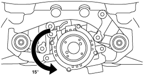
2. Loosen the differential mounting bracket bolt and rotate the bracket as shown in the figure.
3. Rotate the rear differential as shown in the figure, and then remove the rear differential.
Suspension Links Installation Note
1. When installing the joint sections with rubber bushings, perform the following procedures.
- (1) Temporarily tighten the bolts, nuts, and stud bolts with the vehicle lifted up.
-
- (2) Lower the vehicle to the ground and tighten the bolts, nuts, and stud bolts to the specified torque.
-
Rear Differential Mounting Bracket Installation Note
-
Caution
-
• Retighten the rear differential mounting bracket stud bolt when the rear differential mounting bracket nut is loosened.
1. Tighten the rear differential mounting bracket stud bolt.
-
Tightening torque
-
30—37 N·m {3.1—3.7 kgf·m, 23—27 ft·lbf}
 ac5uuw00000879