Note
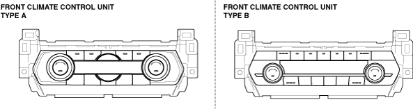
• There are two types of front climate control unit, type A and type B.
ac9wzw00005477
|
AIR FROM FRONT/REAR VENTS NOT COLD ENOUGH [CLIMATE CONTROL SYSTEM]
id0703k2900900
ac9wzw00005477
|
Front Climate Control Unit Type A
|
DESCRIPTION
|
• Magnetic clutch operates but A/C system malfunctions
|
|
POSSIBLE CAUSE
|
• Drive belt malfunction
• Refrigerant pressure sensor malfunction
• Blower unit or condenser malfunction
• Cooling fan system malfunction
• Condenser or related part malfunction
• A/C unit or condenser malfunction
• Receiver/drier or expansion valve malfunction (valve closes too much)
• Refrigerant lines malfunction
• A/C compressor system malfunction, insufficient compressor oil
• Over filling of compressor oil, malfunction in expansion valve or A/C unit air mix link system
• Evaporative temperature sensor malfunction
|
Diagnostic procedure
|
Step |
Inspection |
Action |
|
|---|---|---|---|
|
1
|
CHECK MALFUNCTION SYMPTOMS
• Is malfunctions occur in only when operating the i-stop?
|
Yes
|
Perform the i-stop troubleshooting.
|
|
No
|
Go to the next step.
|
||
|
2
|
INSPECT CLIMATE CONTROL UNIT FOR DTC
• Retrieve the climate control unit DTC using the M-MDS.
• Are there DTC displayed?
|
Yes
|
Go to the applicable DTC troubleshooting procedures.
|
|
No
|
Go to the next step.
|
||
|
3
|
INSPECT REFRIGERANT PRESSURE TO LOCATE MALFUNCTION
• Perform refrigerant pressure check.
(See REFRIGERANT PRESSURE CHECK.)
• Is the refrigerant pressure normal?
|
Yes
|
Go to the next step.
|
|
No
|
Record the inspection result.
• If the refrigerant high-pressure and low-pressure values are both high, go to Step 7.
• If the refrigerant high-pressure and low-pressure values are approximately the same, go to Step 10.
• If the refrigerant high-pressure and low-pressure values are both low, go to Step 12.
• If there is a vacuum on the low pressure side and extremely low pressure on the high pressure side, go to Step 18.
• If there is low pressure on the high pressure side and high pressure on the low pressure side, replace the A/C compressor, then go to Step 22.
• If the refrigerant pressure is other than above condition, go to Step 20.
|
||
|
4
|
INSPECT REFRIGERANT SYSTEM PERFORMANCE
• Perform refrigerant system performance test.
• Is the operation normal?
|
Yes
|
Operation is normal. (Recheck malfunction symptoms.)
|
|
No
|
Go to the next step.
|
||
|
5
|
INSPECT DRIVE BELT
• Inspect the drive belt.
• Is it normal?
|
Yes
|
Go to the next step.
|
|
No
|
Adjust or replace the drive belt, then go to the next step.
|
||
|
6
|
INSPECT REFRIGERANT PRESSURE SENSOR
• Inspect the refrigerant pressure sensor.
• Is it normal?
|
Yes
|
Go to the next step.
|
|
No
|
Repair or replace malfunctioning part according to inspection result, then go to Step 22.
|
||
|
7
|
INSPECT COOLING FAN OPERATION
• Verify the cooling fan operation.
• Is the cooling fan operation normal?
|
Yes
|
Go to the next step.
|
|
No
|
Repair or replace the malfunctioning location according to the inspection results.
Then go to Step 22.
|
||
|
8
|
VISUALLY INSPECT CONDENSER
• Is the condenser fin clogged or obstructed by foreign material?
|
Yes
|
Remove the foreign material.
Repair the condenser fin.
Then go to Step 22.
|
|
No
|
Go to the next step.
|
||
|
9
|
CHECK REFRIGERATION SYSTEM FOR OVERCHARGE OR AIR CONTAMINATION
• Is the low side line hot to the touch?
|
Yes
|
Recover refrigerant. Evacuate system for one hour. Refill with correct amount of refrigerant, and go to Step 22.
|
|
No
|
Recover refrigerant, evacuate for 15 minutes, refill with correct amount and go to Step 22.
|
||
|
10
|
CHECK TO SEE WHETHER MALFUNCTION IS IN EXPANSION VALVE OR ELSEWHERE
• Compare the refrigerant pressure of the low pressure side with the high pressure side at Step 3.
• Is there little difference between the high pressure side and low pressure side readings (refer to graph in REFRIGERANT PRESSURE CHECK procedure)?
(See REFRIGERANT PRESSURE CHECK.)
|
Yes
|
Replace the expansion valve.
After performing the following servicing, go to Step 22.
• Adjust the compressor oil to the specified level.
• After discharging, charge with new refrigerant to the specified level.
|
|
No
|
Go to the next step.
|
||
|
11
|
INSPECT AIR MIX DOOR RELATED PART INSTALLATION
• Measure the voltages at the following terminals (wiring harness-side) when the temperature control dials are set to MAX COLD and MAX HOT.
• Are voltages normal?
|
Yes
|
Adjust the compressor oil to the specified amount, then go to Step 22.
|
|
No
|
• Inspect the air mix link, air mix crank, and air mix rod of the A/C unit correctly and securely installed to their positions.
• Repair or install correctly for suspect part according to inspection result, then go to Step 22.
|
||
|
12
|
INSPECT BLOWER UNIT FOR BLOCKAGE
• Is the blower unit intake and air filter clogged?
(See AIR FILTER INSPECTION.)
|
Yes
|
Remove the cause of the clogging. Replace the air filter if it is clogged.
Then go to Step 22.
|
|
No
|
Go to the next step.
|
||
|
13
|
CHECK TO SEE WHETHER MALFUNCTION IS REFRIGERANT LINE LEAKAGE OR ELSEWHERE
• Verify if there is gas leakage from the system hoses using the gas leak tester.
• Is there gas leakage?
|
Yes
|
• If there is leakage from a system hose connection area, go to Step 15.
• If there is leakage other than from a system hose connection area, go to Step 17.
|
|
No
|
Go to the next step.
|
||
|
14
|
VISUALLY INSPECT REFRIGERANT LINE
• Is a system hose crushed?
|
Yes
|
Replace the crushed system hose.
After performing the following servicing, go to Step 22.
• Adjust the compressor oil to the specified level.
• After discharging, charge with new refrigerant to the specified level.
|
|
No
|
Go to Step 21.
|
||
|
15
|
CHECK TO SEE WHETHER MALFUNCTION IS IN REFRIGERANT LINE JOINT LOOSE OR O-RING
• Tighten the system hose connection area to the specified torque.
• Has the leakage stopped?
|
Yes
|
Go to the next step.
|
|
No
|
Go to Step 17.
|
||
|
16
|
VISUALLY INSPECT REFRIGERANT LINE
• Is a system hose crushed?
|
Yes
|
Replace the crushed system hose.
After performing the following servicing, go to Step 22.
• Adjust the compressor oil to the specified level.
• After discharging, charge with new refrigerant to the specified level.
|
|
No
|
Adjust the compressor oil to the specified amount, then go to Step 22.
|
||
|
17
|
VISUALLY INSPECT REFRIGERANT LINE
• Is a system hose crushed?
|
Yes
|
Replace the O-ring of the leaking area.
Replace the crushed system hose.
After performing the following servicing, go to Step 22.
• Adjust the compressor oil to the specified level.
• After discharging, charge with new refrigerant to the specified level.
|
|
No
|
Replace the O-ring of the leaking area.
After performing the following servicing, go to Step 22.
• Adjust the compressor oil to the specified level.
• After discharging, charge with new refrigerant to the specified level.
|
||
|
18
|
CHECK TO SEE WHETHER MALFUNCTION IS WATER IN REFRIGERANT SYSTEM OR ELSEWHERE
• Is there is no refrigerant pressure on the low pressure side, or is it normal?
(See REFRIGERANT PRESSURE CHECK.)
|
Yes
|
Replace the condenser. (Water in refrigerant system)
Go to Step 22.
|
|
No
|
Go to the next step.
|
||
|
19
|
CHECK TO SEE WHETHER MALFUNCTION IS IN RECEIVER DRYER FILTER OR EXPANSION VALVE
• Remove the expansion valve and verify its condition.
• Is there refrigerant leakage or valve clogging?
|
Yes
|
If there is foreign matter clogging the valve:
• Remove the foreign matter.
If there is refrigerant leakage or clogging:
• Replace the expansion valve.
Perform discharge, charge with new refrigerant, and then go to Step 22.
|
|
No
|
Replace the condenser. (Receiver/Dryer filter is clogged.)
Then go to Step 22.
|
||
|
20
|
INSPECT EVAPORATIVE TEMPERATURE SENSOR
• Inspect the evaporator temperature sensor.
• Is it normal?
|
Yes
|
Verify the evaporator temperature sensor position.
Then go to Step 22.
|
|
No
|
Replace the evaporator temperature sensor.
Then go to Step 22.
|
||
|
21
|
INSPECT AIR MIX DOOR RELATED PART INSTALLATION
• Measure the voltages at the following climate control unit terminals when the temperature control dials are set to MAX COLD and MAX HOT.
• Are voltages normal?
|
Yes
|
Go to the next step.
|
|
No
|
• Inspect the air mix link, air mix crank, and air mix rod of the A/C unit correctly and securely installed to their positions.
• Repair or install correctly for suspect part according to inspection result, then go to next Step.
|
||
|
22
|
VERIFY THAT MALFUNCTION SYMPTOM DOES OCCURS AFTER REPAIR
• If the refrigerant discharged during inspection has not been recharged, discharge and charge with new refrigerant to the specified level.
• Does cool air blow out? (Are results of refrigerant system performance test normal?)
|
Yes
|
Troubleshooting completed. Explain repairs to customer.
|
|
No
|
Recheck malfunction symptoms, then repeat from Step 1 if malfunction recurs.
|
||
Front Climate Control Unit Type B
|
DESCRIPTION
|
• Magnetic clutch operates but A/C system malfunctions
|
|
POSSIBLE CAUSE
|
• Drive belt malfunction
• Refrigerant pressure sensor malfunction
• Blower unit or condenser malfunction
• Cooling fan system malfunction
• Condenser or related part malfunction
• A/C unit or condenser malfunction
• Receiver/drier or expansion valve malfunction (valve closes too much)
• Refrigerant lines malfunction
• A/C compressor system malfunction, insufficient compressor oil
• Over filling of compressor oil, malfunction in expansion valve or A/C unit air mix link system
• Evaporative temperature sensor malfunction
|
Diagnostic procedure
|
Step |
Inspection |
Action |
|
|---|---|---|---|
|
1
|
CHECK MALFUNCTION SYMPTOMS
• Is malfunctions occur in only when operating the i-stop?
|
Yes
|
Perform the i-stop troubleshooting.
|
|
No
|
Go to the next step.
|
||
|
2
|
INSPECT CLIMATE CONTROL UNIT FOR DTC
• Retrieve the climate control unit DTC using the M-MDS.
• Are there DTC displayed?
|
Yes
|
Go to the applicable DTC troubleshooting procedures.
|
|
No
|
Go to the next step.
|
||
|
3
|
INSPECT REFRIGERANT PRESSURE TO LOCATE MALFUNCTION
• Perform refrigerant pressure check.
(See REFRIGERANT PRESSURE CHECK.)
• Is the refrigerant pressure normal?
|
Yes
|
Go to the next step.
|
|
No
|
Record the inspection result.
• If the refrigerant high-pressure and low-pressure values are both high, go to Step 7.
• If the refrigerant high-pressure and low-pressure values are approximately the same, go to Step 10.
• If the refrigerant high-pressure and low-pressure values are both low, go to Step 12.
• If there is a vacuum on the low pressure side and extremely low pressure on the high pressure side, go to Step 18.
• If there is low pressure on the high pressure side and high pressure on the low pressure side, replace the A/C compressor, then go to Step 22.
• If the refrigerant pressure is other than above condition, go to Step 20.
|
||
|
4
|
INSPECT REFRIGERANT SYSTEM PERFORMANCE
• Perform refrigerant system performance test.
• Is the operation normal?
|
Yes
|
Operation is normal. (Recheck malfunction symptoms.)
|
|
No
|
Go to the next step.
|
||
|
5
|
INSPECT DRIVE BELT
• Inspect the drive belt.
• Is it normal?
|
Yes
|
Go to the next step.
|
|
No
|
Adjust or replace the drive belt, then go to the next step.
|
||
|
6
|
INSPECT REFRIGERANT PRESSURE SENSOR
• Inspect the refrigerant pressure sensor.
• Is it normal?
|
Yes
|
Go to the next step.
|
|
No
|
Repair or replace malfunctioning part according to inspection result, then go to Step 22.
|
||
|
7
|
INSPECT COOLING FAN OPERATION
• Verify the cooling fan operation.
• Is the cooling fan operation normal?
|
Yes
|
Go to the next step.
|
|
No
|
Repair or replace the malfunctioning location according to the inspection results.
Then go to Step 22.
|
||
|
8
|
VISUALLY INSPECT CONDENSER
• Is the condenser fin clogged or obstructed by foreign material?
|
Yes
|
Remove the foreign material.
Repair the condenser fin.
Then go to Step 22.
|
|
No
|
Go to the next step.
|
||
|
9
|
CHECK REFRIGERATION SYSTEM FOR OVERCHARGE OR AIR CONTAMINATION
• Is the low side line hot to the touch?
|
Yes
|
Recover refrigerant. Evacuate system for one hour. Refill with correct amount of refrigerant, and go to Step 22.
|
|
No
|
Recover refrigerant, evacuate for 15 minutes, refill with correct amount and go to Step 22.
|
||
|
10
|
CHECK TO SEE WHETHER MALFUNCTION IS IN EXPANSION VALVE OR ELSEWHERE
• Compare the refrigerant pressure of the low pressure side with the high pressure side at Step 3.
• Is there little difference between the high pressure side and low pressure side readings (refer to graph in REFRIGERANT PRESSURE CHECK procedure)?
(See REFRIGERANT PRESSURE CHECK.)
|
Yes
|
Replace the expansion valve.
After performing the following servicing, go to Step 22.
• Adjust the compressor oil to the specified level.
• After discharging, charge with new refrigerant to the specified level.
|
|
No
|
Go to the next step.
|
||
|
11
|
INSPECT AIR MIX DOOR RELATED PART INSTALLATION
• Measure the voltages at the following terminals (wiring harness-side) when the temperature control dials are set to MAX COLD and MAX HOT.
• Are voltages normal?
|
Yes
|
Adjust the compressor oil to the specified amount, then go to Step 22.
|
|
No
|
• Inspect the air mix link, air mix crank, and air mix rod of the A/C unit correctly and securely installed to their positions.
• Repair or install correctly for suspect part according to inspection result, then go to Step 22.
|
||
|
12
|
INSPECT BLOWER UNIT FOR BLOCKAGE
• Is the blower unit intake and air filter clogged?
(See AIR FILTER INSPECTION.)
|
Yes
|
Remove the cause of the clogging. Replace the air filter if it is clogged.
Then go to Step 22.
|
|
No
|
Go to the next step.
|
||
|
13
|
CHECK TO SEE WHETHER MALFUNCTION IS REFRIGERANT LINE LEAKAGE OR ELSEWHERE
• Verify if there is gas leakage from the system hoses using the gas leak tester.
• Is there gas leakage?
|
Yes
|
• If there is leakage from a system hose connection area, go to Step 15.
• If there is leakage other than from a system hose connection area, go to Step 17.
|
|
No
|
Go to the next step.
|
||
|
14
|
VISUALLY INSPECT REFRIGERANT LINE
• Is a system hose crushed?
|
Yes
|
Replace the crushed system hose.
After performing the following servicing, go to Step 22.
• Adjust the compressor oil to the specified level.
• After discharging, charge with new refrigerant to the specified level.
|
|
No
|
Go to Step 21.
|
||
|
15
|
CHECK TO SEE WHETHER MALFUNCTION IS IN REFRIGERANT LINE JOINT LOOSE OR O-RING
• Tighten the system hose connection area to the specified torque.
• Has the leakage stopped?
|
Yes
|
Go to the next step.
|
|
No
|
Go to Step 17.
|
||
|
16
|
VISUALLY INSPECT REFRIGERANT LINE
• Is a system hose crushed?
|
Yes
|
Replace the crushed system hose.
After performing the following servicing, go to Step 22.
• Adjust the compressor oil to the specified level.
• After discharging, charge with new refrigerant to the specified level.
|
|
No
|
Adjust the compressor oil to the specified amount, then go to Step 22.
|
||
|
17
|
VISUALLY INSPECT REFRIGERANT LINE
• Is a system hose crushed?
|
Yes
|
Replace the O-ring of the leaking area.
Replace the crushed system hose.
After performing the following servicing, go to Step 22.
• Adjust the compressor oil to the specified level.
• After discharging, charge with new refrigerant to the specified level.
|
|
No
|
Replace the O-ring of the leaking area.
After performing the following servicing, go to Step 22.
• Adjust the compressor oil to the specified level.
• After discharging, charge with new refrigerant to the specified level.
|
||
|
18
|
CHECK TO SEE WHETHER MALFUNCTION IS WATER IN REFRIGERANT SYSTEM OR ELSEWHERE
• Is there is no refrigerant pressure on the low pressure side, or is it normal?
(See REFRIGERANT PRESSURE CHECK.)
|
Yes
|
Replace the condenser. (Water in refrigerant system)
Go to Step 22.
|
|
No
|
Go to the next step.
|
||
|
19
|
CHECK TO SEE WHETHER MALFUNCTION IS IN RECEIVER DRYER FILTER OR EXPANSION VALVE
• Remove the expansion valve and verify its condition.
• Is there refrigerant leakage or valve clogging?
|
Yes
|
If there is foreign matter clogging the valve:
• Remove the foreign matter.
If there is refrigerant leakage or clogging:
• Replace the expansion valve.
Perform discharge, charge with new refrigerant, and then go to Step 22.
|
|
No
|
Replace the condenser. (Receiver/Dryer filter is clogged.)
Then go to Step 22.
|
||
|
20
|
INSPECT EVAPORATIVE TEMPERATURE SENSOR
• Inspect the evaporator temperature sensor.
• Is it normal?
|
Yes
|
Verify the evaporator temperature sensor position.
Then go to Step 22.
|
|
No
|
Replace the evaporator temperature sensor.
Then go to Step 22.
|
||
|
21
|
INSPECT AIR MIX DOOR RELATED PART INSTALLATION
• Measure the voltages at the following climate control unit terminals when the temperature control dials are set to MAX COLD and MAX HOT.
• Are voltages normal?
|
Yes
|
Go to the next step.
|
|
No
|
• Inspect the air mix link, air mix crank, and air mix rod of the A/C unit correctly and securely installed to their positions.
• Repair or install correctly for suspect part according to inspection result, then go to next Step.
|
||
|
22
|
VERIFY THAT MALFUNCTION SYMPTOM DOES OCCURS AFTER REPAIR
• If the refrigerant discharged during inspection has not been recharged, discharge and charge with new refrigerant to the specified level.
• Does cool air blow out? (Are results of refrigerant system performance test normal?)
|
Yes
|
Troubleshooting completed. Explain repairs to customer.
|
|
No
|
Recheck malfunction symptoms, then repeat from Step 1 if malfunction recurs.
|
||