FRONT A/C UNIT REMOVAL/INSTALLATION
id071100802500
L.H.D.
-
Warning
-
• Handling the driver-side air bag module improperly can accidentally operate (deploy) the air bag module, which may seriously injure you. Read the air bag system service warnings and cautions before handling the driver-side air bag module. (See
AIR BAG SYSTEM SERVICE WARNINGS.) (See
AIR BAG SYSTEM SERVICE CAUTIONS.)
-
Note
-
• When removing the driver-side air bag module, it is necessary to rotate the steering wheel.If the ignition has been switched off with the driver's door closed, the steering wheel will be locked.Perform the procedure from Steps 1-3 so that the steering wheel will not be locked.
1. Switch the ignition ON (engine off or on).
2. Open the driver's door.
3. Switch the ignition off.
4. Disconnect the negative battery terminal and wait for 1 min or more. (See NEGATIVE BATTERY TERMINAL DISCONNECTION/CONNECTION.)
5. Discharge the refrigerant. (See REFRIGERANT RECOVERY.)(See REFRIGERANT CHARGING.)
6. Drain the engine coolant. (See ENGINE COOLANT REPLACEMENT [SKYACTIV-G 2.5T].)
7. Remove the following parts:
- (1) Plug hole plate (See PLUG HOLE PLATE REMOVAL/INSTALLATION [SKYACTIV-G 2.5T].)
-
- (2) Windshield wiper arm and blade (See WINDSHIELD WIPER ARM AND BLADE REMOVAL/INSTALLATION.)
-
- (3) Cowl grille (See COWL GRILLE REMOVAL/INSTALLATION.)
-
- (4) Front scuff plate (See FRONT SCUFF PLATE REMOVAL/INSTALLATION.)
-
- (5) Front side trim (See FRONT SIDE TRIM REMOVAL/INSTALLATION.)
-
- (6) Glove compartment (See GLOVE COMPARTMENT REMOVAL/INSTALLATION.)
-
- (7) Dashboard under cover (See DASHBOARD UNDER COVER REMOVAL/INSTALLATION.)
-
- (8) Passenger-side decoration panel (See DECORATION PANEL REMOVAL/INSTALLATION.)
-
- (9) A-pillar trim (See A-PILLAR TRIM REMOVAL/INSTALLATION.)
-
- (10) Driver-side air bag module (See DRIVER-SIDE AIR BAG MODULE REMOVAL.)(See DRIVER-SIDE AIR BAG MODULE INSTALLATION.)
-
- (11) Steering wheel (See STEERING WHEEL AND COLUMN REMOVAL/INSTALLATION.)
-
- (12) Upper column cover (See COLUMN COVER REMOVAL/INSTALLATION.)
-
- (13) Meter hood (See METER HOOD REMOVAL/INSTALLATION.)
-
- (14) Instrument cluster (See INSTRUMENT CLUSTER REMOVAL/INSTALLATION.)
-
- (15) Lower column cover (See COLUMN COVER REMOVAL/INSTALLATION.)
-
- (16) Clock spring (See CLOCK SPRING REMOVAL/INSTALLATION.)
-
- (17) Wiper and washer switch (See WIPER AND WASHER SWITCH REMOVAL/INSTALLATION.)
-
- (18) Light switch (See LIGHT SWITCH REMOVAL/INSTALLATION.)
-
- (19) Bonnet release lever (See BONNET RELEASE LEVER AND RELEASE CABLE REMOVAL/INSTALLATION.)
-
- (20) Fuel-filler lid opener lever (See FUEL-FILLER LID OPENER AND LEVER REMOVAL/INSTALLATION.)
-
- (21) Driver-side lower panel (See DRIVER-SIDE LOWER PANEL REMOVAL/INSTALLATION.)
-
- (22) Joint cover (See STEERING WHEEL AND COLUMN REMOVAL/INSTALLATION.)
-
- (23) Steering shaft (See STEERING WHEEL AND COLUMN REMOVAL/INSTALLATION.)
-
- (24) Selector lever knob (See AUTOMATIC TRANSAXLE SHIFT MECHANISM REMOVAL/INSTALLATION.)
-
- (25) Shift panel (See SHIFT PANEL REMOVAL/INSTALLATION.)
-
- (26) Console side panel (See CONSOLE SIDE PANEL REMOVAL/INSTALLATION.)
-
- (27) Front console (See FRONT CONSOLE REMOVAL/INSTALLATION.)
-
- (28) Side wall (See SIDE WALL REMOVAL/INSTALLATION.)
-
- (29) Rear console (See REAR CONSOLE REMOVAL/INSTALLATION.)
-
- (30) Selector lever component (See AUTOMATIC TRANSAXLE SHIFT MECHANISM REMOVAL/INSTALLATION.)
-
- (31) Selector lever bracket (See AUTOMATIC TRANSAXLE SHIFT MECHANISM REMOVAL/INSTALLATION.)
-
- (32) Passenger-side lower panel (See PASSENGER-SIDE LOWER PANEL REMOVAL/INSTALLATION.)
-
- (33) Front climate control unit (See FRONT CLIMATE CONTROL UNIT REMOVAL/INSTALLATION.)
-
- (34) Center display (See CENTER DISPLAY REMOVAL/INSTALLATION.)
-
- (35) Connectivity master unit (CMU) (See CONNECTIVITY MASTER UNIT (CMU) REMOVAL/INSTALLATION.)
-
- (36) Dashboard (See DASHBOARD REMOVAL.)(See DASHBOARD INSTALLATION.)
-
- (37) Front heat duct (See FRONT HEAT DUCT REMOVAL/INSTALLATION.)
-
- (38) Blower unit (See BLOWER UNIT REMOVAL/INSTALLATION.)
-
- (39) Foot support (See FOOT SUPPORT REMOVAL/INSTALLATION.)
-
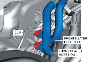
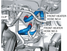
8. Disconnect the front heater hose No.4.
9. Disconnect the front heater hose No.3.
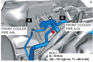
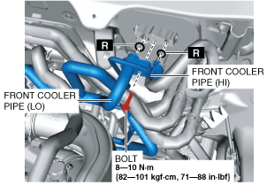
10. Remove the bolt.
11. Disconnect the front cooler pipe (LO) and front cooler pipe (HI). Do not allow compressor oil to spill.
-
Caution
-
• If moisture or foreign matter enters the refrigeration cycle, cooling ability will be lowered and abnormal noise or other malfunctions could occur. Always plug open fittings immediately after removing any refrigeration cycle parts.
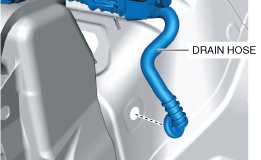
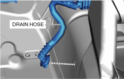
12. Disconnect the drain hose.
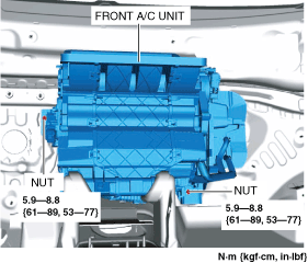
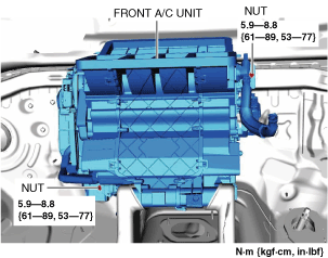
13. Remove the nuts.
14. Remove the front A/C unit. Do not allow compressor oil to spill.
15. Install in the reverse order of removal. (See Front A/C unit installation note (1).)(See Front A/C unit installation note (2).)
16. Inspect for engine coolant leakage. (See ENGINE COOLANT LEAKAGE INSPECTION [SKYACTIV-G 2.5T].)
17. Perform the refrigerant system performance test. (See REFRIGERANT SYSTEM PERFORMANCE TEST.)
Front A/C unit installation note (1)
1. Apply compressor oil to the O-rings and connect the joints.
Front A/C unit installation note (2)
1. When replacing the front A/C unit or front evaporator, add compressor oil to the refrigerant cycle.
-
Supplemental oil amount (approx. quantity)
-
40 ml {40 cc, 1.4 US fl oz}
R.H.D.
-
Warning
-
• Handling the driver-side air bag module improperly can accidentally operate (deploy) the air bag module, which may seriously injure you. Read the air bag system service warnings and cautions before handling the driver-side air bag module. (See
AIR BAG SYSTEM SERVICE WARNINGS.) (See
AIR BAG SYSTEM SERVICE CAUTIONS.)
-
Note
-
• When removing the driver-side air bag module, it is necessary to rotate the steering wheel.If the ignition has been switched off with the driver's door closed, the steering wheel will be locked.Perform the procedure from Steps 1-3 so that the steering wheel will not be locked.
1. Switch the ignition ON (engine off or on).
2. Open the driver's door.
3. Switch the ignition off.
4. Disconnect the negative battery terminal and wait for 1 min or more. (See NEGATIVE BATTERY TERMINAL DISCONNECTION/CONNECTION.)
5. Discharge the refrigerant. (See REFRIGERANT RECOVERY.)(See REFRIGERANT CHARGING.)
6. Drain the engine coolant. (See ENGINE COOLANT REPLACEMENT [SKYACTIV-G 2.5T].)
7. Remove the following parts:
- (1) Plug hole plate (See PLUG HOLE PLATE REMOVAL/INSTALLATION [SKYACTIV-G 2.5T].)
-
- (2) Battery (See BATTERY REMOVAL/INSTALLATION.)
-
- (3) Windshield wiper arm and blade (See WINDSHIELD WIPER ARM AND BLADE REMOVAL/INSTALLATION.)
-
- (4) Cowl grille (See COWL GRILLE REMOVAL/INSTALLATION.)
-
- (5) Front scuff plate (See FRONT SCUFF PLATE REMOVAL/INSTALLATION.)
-
- (6) Front side trim (See FRONT SIDE TRIM REMOVAL/INSTALLATION.)
-
- (7) Glove compartment (See GLOVE COMPARTMENT REMOVAL/INSTALLATION.)
-
- (8) Dashboard under cover (See DASHBOARD UNDER COVER REMOVAL/INSTALLATION.)
-
- (9) Passenger-side decoration panel (See DECORATION PANEL REMOVAL/INSTALLATION.)
-
- (10) A-pillar trim (See A-PILLAR TRIM REMOVAL/INSTALLATION.)
-
- (11) Driver-side air bag module (See DRIVER-SIDE AIR BAG MODULE REMOVAL.)(See DRIVER-SIDE AIR BAG MODULE INSTALLATION.)
-
- (12) Steering wheel (See STEERING WHEEL AND COLUMN REMOVAL/INSTALLATION.)
-
- (13) Upper column cover (See COLUMN COVER REMOVAL/INSTALLATION.)
-
- (14) Meter hood (See METER HOOD REMOVAL/INSTALLATION.)
-
- (15) Instrument cluster (See INSTRUMENT CLUSTER REMOVAL/INSTALLATION.)
-
- (16) Lower column cover (See COLUMN COVER REMOVAL/INSTALLATION.)
-
- (17) Clock spring (See CLOCK SPRING REMOVAL/INSTALLATION.)
-
- (18) Wiper and washer switch (See WIPER AND WASHER SWITCH REMOVAL/INSTALLATION.)
-
- (19) Light switch (See LIGHT SWITCH REMOVAL/INSTALLATION.)
-
- (20) Bonnet release lever (See BONNET RELEASE LEVER AND RELEASE CABLE REMOVAL/INSTALLATION.)
-
- (21) Fuel-filler lid opener lever (See FUEL-FILLER LID OPENER AND LEVER REMOVAL/INSTALLATION.)
-
- (22) Driver-side lower panel (See DRIVER-SIDE LOWER PANEL REMOVAL/INSTALLATION.)
-
- (23) Joint cover (See STEERING WHEEL AND COLUMN REMOVAL/INSTALLATION.)
-
- (24) Steering shaft (See STEERING WHEEL AND COLUMN REMOVAL/INSTALLATION.)
-
- (25) Selector lever knob (See AUTOMATIC TRANSAXLE SHIFT MECHANISM REMOVAL/INSTALLATION.)
-
- (26) Shift panel (See SHIFT PANEL REMOVAL/INSTALLATION.)
-
- (27) Console side panel (See CONSOLE SIDE PANEL REMOVAL/INSTALLATION.)
-
- (28) Front console (See FRONT CONSOLE REMOVAL/INSTALLATION.)
-
- (29) Side wall (See SIDE WALL REMOVAL/INSTALLATION.)
-
- (30) Rear console (See REAR CONSOLE REMOVAL/INSTALLATION.)
-
- (31) Selector lever component (See AUTOMATIC TRANSAXLE SHIFT MECHANISM REMOVAL/INSTALLATION.)
-
- (32) Selector lever bracket (See AUTOMATIC TRANSAXLE SHIFT MECHANISM REMOVAL/INSTALLATION.)
-
- (33) Passenger-side lower panel (See PASSENGER-SIDE LOWER PANEL REMOVAL/INSTALLATION.)
-
- (34) Front climate control unit (See FRONT CLIMATE CONTROL UNIT REMOVAL/INSTALLATION.)
-
- (35) Center display (See CENTER DISPLAY REMOVAL/INSTALLATION.)
-
- (36) Connectivity master unit (CMU) (See CONNECTIVITY MASTER UNIT (CMU) REMOVAL/INSTALLATION.)
-
- (37) Dashboard (See DASHBOARD REMOVAL.)(See DASHBOARD INSTALLATION.)
-
- (38) Front heat duct (See FRONT HEAT DUCT REMOVAL/INSTALLATION.)
-
- (39) Blower unit (See BLOWER UNIT REMOVAL/INSTALLATION.)
-
- (40) Foot support (See FOOT SUPPORT REMOVAL/INSTALLATION.)
-
8. Disconnect the front heater hose No.4.
9. Disconnect the front heater hose No.3.
10. Remove the bolt.
11. Disconnect the front cooler pipe (LO) and front cooler pipe (HI). Do not allow compressor oil to spill.
-
Caution
-
• If moisture or foreign matter enters the refrigeration cycle, cooling ability will be lowered and abnormal noise or other malfunctions could occur. Always plug open fittings immediately after removing any refrigeration cycle parts.
12. Disconnect the drain hose.
13. Remove the nuts.
14. Remove the front A/C unit. Do not allow compressor oil to spill.
15. Install in the reverse order of removal. (See Front A/C unit installation note (1).)(See Front A/C unit installation note (2).)
16. Inspect for engine coolant leakage. (See ENGINE COOLANT LEAKAGE INSPECTION [SKYACTIV-G 2.5T].)
17. Perform the refrigerant system performance test. (See REFRIGERANT SYSTEM PERFORMANCE TEST.)
Front A/C unit installation note (1)
1. Apply compressor oil to the O-rings and connect the joints.
Front A/C unit installation note (2)
1. When replacing the front A/C unit or front evaporator, add compressor oil to the refrigerant cycle.
-
Supplemental oil amount (approx. quantity)
-
40 ml {40 cc, 1.4 US fl oz}