1: –
2: MAZ-95-130-KT
Dual purpose diagnostic leak detector
ENGINE CONTROL SYSTEM OPERATION INSPECTION [SKYACTIV-G 2.5T]
id0103q4803700
Special Service Tool (SST)
|
1: –
2: MAZ-95-130-KT
Dual purpose diagnostic leak detector
|
|
Main Relay Operation Inspection
1. Verify that the main relay clicks when the ignition is switched ON and then off.
Intake Manifold Vacuum Inspection
1. Disconnect the vacuum hose and install the vacuum gauge. (See CHECK VALVE (EMISSION SYSTEM) REMOVAL/INSTALLATION [SKYACTIV-G 2.5T].)
2. Verify that the intake air hoses are installed securely.
3. Warm up the engine.
4. Measure the intake manifold vacuum while idling (no load) using the vacuum gauge.
Electric Variable Valve Timing Driver Control System Inspection
1. Connect the M-MDS to the DLC-2.
2. Perform the KOER self test. (See KOEO/KOER SELF TEST [PCM (SKYACTIV-G 2.5T)].)
3. Verify that DTC P0010:00 or P1380:00 is not displayed. (See ON-BOARD DIAGNOSTIC TEST [PCM (SKYACTIV-G 2.5T)].)
4. Perform the Drive Mode 03 (Variable Valve Timing, A/F Sensor, HO2S and TWC Repair Verification Drive Mode). (See OBD DRIVE MODE [PCM (SKYACTIV-G 2.5T)].)
5. Verify that DTC P0011:00 or P0012:00 is not displayed. (See ON-BOARD DIAGNOSTIC TEST [PCM (SKYACTIV-G 2.5T)].)
6. Access the following PCM PIDs using the M-MDS. (See ON-BOARD DIAGNOSTIC TEST [PCM (SKYACTIV-G 2.5T)].)
7. Accelerate and decelerate the vehicle, and drive at normal speed, and verify that the data monitor item VT_IN_ACT value changes in conjunction with the VT_IN_DES value.
Engine Oil Solenoid Valve Control System Inspection
1. Connect the M-MDS to the DLC-2.
2. Perform the KOER self test. (See KOEO/KOER SELF TEST [PCM (SKYACTIV-G 2.5T)].)
3. Verify that DTC P06DB:00 or P06DC:00 is not displayed. (See ON-BOARD DIAGNOSTIC TEST [PCM (SKYACTIV-G 2.5T)].)
4. Inspect the engine oil pressure. (See OIL PRESSURE INSPECTION [SKYACTIV-G 2.5T].)
5. Access the following PCM PIDs using the M-MDS. (See ON-BOARD DIAGNOSTIC TEST [PCM (SKYACTIV-G 2.5T)].)
6. With the engine coolant temperature at 98 °C {208 °F}, increase the engine speed to 4,000 rpm or higher, and verify that the oil pressure gauge value changes when the data monitor item OIL_P_SOL value is changed from ON to OFF.
Drive-by-wire Control System Inspection
Engine coolant temperature compensation inspection
1. Connect the M-MDS to the DLC-2.
2. Select the following PIDs: (See ON-BOARD DIAGNOSTIC TEST [PCM (SKYACTIV-G 2.5T)].)
3. Verify that the engine is cold, then start the engine.
4. Verify that the engine speed decreases as the engine warms up.
Load compensation inspection
1. Start the engine and let it idle.
2. Connect the M-MDS to the DLC-2.
3. Select the RPM PID.
4. Verify that the engine speed is within specification under each load condition.
Electronic Control Throttle Operation Inspection
1. Connect the M-MDS to the DLC-2.
2. Perform the KOEO and KOER self test. (See KOEO/KOER SELF TEST [PCM (SKYACTIV-G 2.5T)].)
3. Verify that none of the following DTCs are displayed:
4. Access the following PCM PIDs using the M-MDS. (See ON-BOARD DIAGNOSTIC TEST [PCM (SKYACTIV-G 2.5T)].)
5. With the accelerator pedal not depressed and with it depressed to the floor, verify that the data monitor item ETC_ACT value changes in conjunction with the ETC_DSD value.
Brake override system operation inspection
1. Start the engine and let it idle.
2. Verify that the engine speed becomes less than 1,200 rpm under the following conditions.
Wastegate Valve Operation Inspection
1. Connect the M-MDS to the DLC-2.
2. Perform the KOEO or KOER self test. (See KOEO/KOER SELF TEST [PCM (SKYACTIV-G 2.5T)].)
3. Verify that DTC P0045:00 or P0046:00 is not displayed. (See ON-BOARD DIAGNOSTIC TEST [PCM (SKYACTIV-G 2.5T)].)
4. Access the following PCM PIDs using the M-MDS. (See ON-BOARD DIAGNOSTIC TEST [PCM (SKYACTIV-G 2.5T)].)
5. Accelerate and decelerate the vehicle, and drive at normal speed, and verify that the data monitor item WGV_ACT value changes in conjunction with the WGV_DSD value.
Fuel Injector Operation Inspection
If simulation function of M-MDS is used:
|
STEP |
INSPECTION |
ACTION |
|
|---|---|---|---|
|
1
|
Start the engine and warm it up completely.
Access the INJ_1, INJ_2, INJ_3 and INJ_4 PIDs using the M-MDS.
Turn each fuel injector from on to off using the PIDs for each cylinder.
Does the engine speed drop?
|
Yes
|
Fuel injectors work properly.
|
|
No
|
Engine speed does not drop an any cylinder:
• Go to the next step.
Engine speed drops on some cylinders:
• Go to Step 4.
|
||
|
2
|
Perform the Main Relay Operation Inspection.
Does the main relay work properly?
|
Yes
|
Go to the next step.
|
|
No
|
Repair or replace the malfunctioning part according to the inspection results.
|
||
|
3
|
Inspect the fuel injector of the suspected cylinder.
Is there any malfunction?
|
Yes
|
Replace the fuel injector.
|
|
No
|
Inspect the fuel injector power and/or ground systems related wiring harness and connectors for the suspected cylinder.
• If all items normal:
• If not:
|
||
|
4
|
Perform the KOER self test using the M-MDS.
Are the DTCs P0201:00, P0202:00, P0203:00 and/or P0204:00 present?
|
Yes
|
Go to the appropriate DTC inspection.
|
|
No
|
Go to the next step.
|
||
|
5
|
Inspect the fuel injector of the suspected cylinder.
Is there any malfunction?
|
Yes
|
Replace the fuel injector.
|
|
No
|
Inspect the following for the suspected cylinder:
• PCM terminals (pulled-out pins, corrosion)
• Fuel injector terminals (pulled-out pins, corrosion)
• If all items normal:
• If not:
|
||
If simulation function of M-MDS is not used:
|
STEP |
INSPECTION |
ACTION |
|
|---|---|---|---|
|
1
|
Inspect the fuel injector of the suspected cylinder.
Is there any malfunction?
|
Yes
|
Replace the fuel injector.
|
|
No
|
Go to the next step.
|
||
|
2
|
Inspect the following for the suspected cylinder:
• Fuel injector power and/or ground system related wiring harnesses and connectors
• PCM terminals (pulled-out pins, corrosion)
• Fuel injector terminals (pulled-out pins, corrosion)
Is there any malfunction?
|
Yes
|
Repair or replace the malfunctioning part according to the inspection results.
|
|
No
|
Replace the PCM.
|
||
Fuel Cut Control System Inspection
If data monitor function of M-MDS is used:
1. Warm up the engine and idle it.
2. Connect the M-MDS to the DLC-2.
3. Select the RPM and the FUELPW PIDs. (See ON-BOARD DIAGNOSTIC TEST [PCM (SKYACTIV-G 2.5T)].)
4. Monitor both PIDs while performing the following steps:
If data monitor function of M-MDS is not used:
1. Warm up the engine and idle it.
2. Measure the fuel injector control signal wave profile using the oscilloscope while performing the following steps:
Fuel Pump (Low-pressure Side) Operation Inspection
1. Connect the M-MDS to the DLC-2.
2. Remove the fuel-filler cap.
3. Switch the ignition ON (engine off).
4. Turn the fuel pump relay from off to on using the FP simulation item and inspect if the operation sound of the fuel pump is heard. (See ON-BOARD DIAGNOSTIC TEST [PCM (SKYACTIV-G 2.5T)].)
5. Measure the voltage at the wiring harness side fuel pump unit terminal A with the FP PID turned on.
Fuel Pump (Low-pressure Side) Control System Inspection
If simulation function of M-MDS is used:
1. Connect the M-MDS to the DLC-2.
2. Switch the ignition ON (engine off).
3. Select the FP simulation item. (See ON-BOARD DIAGNOSTIC TEST [PCM (SKYACTIV-G 2.5T)].)
4. Turn the fuel pump relay from off to on and inspect if the operation sound of the fuel pump relay is heard.
If simulation function of M-MDS is not used:
1. Crank the engine and verify that the fuel pump relay operation sound is heard.
2. If the operation sound is not heard, inspect the following:
Spark Test
1. Disconnect the fuel pump relay and fuel injector relay.
2. Verify that each ignition coil and connector is connected properly.
3. Inspect the ignition system in the following procedure:
|
STEP |
INSPECTION |
ACTION |
|
|---|---|---|---|
|
1
|
Disconnect the ignition coils from the spark plugs.
Remove the spark plugs.
Verify that the spark plugs do not have carbon deposits.
Is there any malfunction?
|
Yes
|
Perform no-load racing at 4,000 rpm for 2 min, 2 times to burn off the carbon deposits.
Repeat this step.
|
|
No
|
Go to the next step.
|
||
|
2
|
Inspect the spark plugs for damage, wear, and proper plug gap.
Is there any malfunction?
|
Yes
|
Re-gap or replace the spark plugs, then go to the next step.
|
|
No
|
Go to the next step.
|
||
|
3
|
Reconnect the spark plugs to the ignition coil.
Ground the spark plugs to the engine.
Is a strong blue spark visible at each cylinder while cranking the engine?
|
Yes
|
Ignition system is normal.
|
|
No
|
Some cylinders do not spark:
• Go to the next step.
All cylinders do not spark:
• Go to Step 5.
|
||
|
4
|
Switch the ignition off.
Inspect the wiring harness between the following terminals (wiring harness-side) for an open or short circuit:
• Ignition coil/ion sensor No.1 terminal B—PCM terminal 1AG
• Ignition coil/ion sensor No.2 terminal B—PCM terminal 1AE
• Ignition coil/ion sensor No.3 terminal B—PCM terminal 1AF
• Ignition coil/ion sensor No.4 terminal B—PCM terminal 1AD
Is there any malfunction?
|
Yes
|
Refer to the wiring diagram and verify whether or not there is a common connector between the following terminals:
• Ignition coil/ion sensor No.1 terminal B—PCM terminal 1AG
• Ignition coil/ion sensor No.2 terminal B—PCM terminal 1AE
• Ignition coil/ion sensor No.3 terminal B—PCM terminal 1AF
• Ignition coil/ion sensor No.4 terminal B—PCM terminal 1AD
If there is a common connector:
• Determine the malfunctioning part by inspecting the common connector and the terminal for corrosion, damage, or pin disconnection, and the common wiring harness for an open or short circuit.
• Repair or replace the malfunctioning part.
If there is no common connector:
• Repair or replace the wiring harness which has an open or short circuit.
|
|
No
|
Inspect the ignition coil.
• Replace the ignition coil/ion sensor.
|
||
|
5
|
Switch the ignition off.
Disconnect the ignition coil/ion sensor connectors.
Switch the ignition ON (engine off).
Measure the voltage at each ignition coil/ion sensor terminal A (wiring harness-side).
Is the voltage B+?
|
Yes
|
Go to the next step.
|
|
No
|
Inspect for power supply circuit in wiring harness between main relay and ignition coils.
Refer to the wiring diagram and verify whether or not there is a common connector between the following terminals:
• Main relay terminal C—Ignition coil/ion sensor No.1 terminal A
• Main relay terminal C—Ignition coil/ion sensor No.2 terminal A
• Main relay terminal C—Ignition coil/ion sensor No.3 terminal A
• Main relay terminal C—Ignition coil/ion sensor No.4 terminal A
If there is a common connector:
• Determine the malfunctioning part by inspecting the common connector and the terminal for corrosion, damage, or pin disconnection, and the common wiring harness for a short to power supply.
• Repair or replace the malfunctioning part.
If there is no common connector:
• Repair or replace the wiring harness which has a short to power supply.
|
||
|
6
|
Switch the ignition off.
Inspect for continuity between terminal D (wiring harness-side) in each ignition coils and body ground.
Is there continuity?
|
Yes
|
Go to the next step.
|
|
No
|
Refer to the wiring diagram and verify whether or not there is a common connector between the following terminals:
• Ignition coil/ion sensor No.1 terminal D—Body ground
• Ignition coil/ion sensor No.2 terminal D—Body ground
• Ignition coil/ion sensor No.3 terminal D—Body ground
• Ignition coil/ion sensor No.4 terminal D—Body ground
If there is a common connector:
• Determine the malfunctioning part by inspecting the common connector and the terminal for corrosion, damage, or pin disconnection, and the common wiring harness for an open circuit.
• Repair or replace the malfunctioning part.
If there is no common connector:
• Inspect for the following:
Repeat from Step 1.
|
||
|
7
|
Inspect the connection of PCM and ignition coil/ion sensor connectors.
Does the PCM connector or ignition coil/ion sensor connectors have poor connection?
|
Yes
|
Repair or replace the connector.
Repeat from Step 1.
|
|
No
|
Go to the next step.
|
||
|
8
|
Inspect the CKP sensor and crankshaft pulley.
Is there any malfunction?
|
Yes
|
Repair or replace the malfunctioning part according to the inspection results.
|
|
No
|
Inspect for an open or short circuit in wiring harness and connector of the CKP sensor.
Repair or replace the malfunctioning part according to the inspection results.
|
||
Purge Control System Inspection
If simulation function of M-MDS is used:
1. Start the engine.
2. Remove the plug hole plate. (See PLUG HOLE PLATE REMOVAL/INSTALLATION [SKYACTIV-G 2.5T].)
3. Disconnect the evaporative hose between the purge solenoid valve and the charcoal canister.
4. Put a finger to the purge solenoid valve and verify that there is no vacuum applied when the engine is cold.
5. Connect the M-MDS to the DLC-2 and verify that DTC P0443:00 is displayed. (See DTC P0443:00 [PCM (SKYACTIV-G 2.5T)].)
6. Select the EVAPCP simulation item. (See ON-BOARD DIAGNOSTIC TEST [PCM (SKYACTIV-G 2.5T)].)
7. Increase the duty value of the purge solenoid valve to 50 % and inspect if the operation sound of the valve is heard.
8. Warm up the engine to normal operating temperature.
9. Monitor the EVAPCP PID using the M-MDS, and drive the vehicle approx. 2,000 rpm for 30 s or more. (See ON-BOARD DIAGNOSTIC TEST [PCM (SKYACTIV-G 2.5T)].)
If simulation function of M-MDS is not used:
1. Start the engine.
2. Remove the plug hole plate. (See PLUG HOLE PLATE REMOVAL/INSTALLATION [SKYACTIV-G 2.5T].)
3. Disconnect the evaporative hose between the purge solenoid valve and the charcoal canister.
4. Put a finger to the purge solenoid valve and verify that there is no vacuum applied when the engine is cold.
5. Set the vehicle on a dynamometer or chassis roller.
6. Drive the vehicle at an engine speed to approx. 2,000 rpm for 30 s or more.
7. Put a finger to the purge solenoid valve and verify that there is no vacuum applied during Step 3.
EGR Valve Operation Inspection
1. Verify that the MAP sensor is normal. (See MANIFOLD ABSOLUTE PRESSURE (MAP) SENSOR INSPECTION [SKYACTIV-G 2.5T].)
2. Connect the M-MDS to the DLC-2.
3. Start the engine.
4. Access the following PCM PIDs using the M-MDS. (See ON-BOARD DIAGNOSTIC TEST [PCM (SKYACTIV-G 2.5T)].)
5. Verify the SEGRP PID value when the simulation item SEGRP_DSD increases from 0 % to 100 %.
A/C Cut-off Control System Inspection
1. Start the engine.
2. Turn the A/C switch on.
3. Verify that the A/C compressor magnetic clutch actuates.
4. Fully open the throttle valve and verify that the A/C compressor magnetic clutch does not actuate for 2—5 s.
Cooling Fan Control System Inspection
1. Connect the M-MDS to the DLC-2.
2. Start the engine and warm it up to normal operating temperature.
3. Perform the KOER self test. (See KOEO/KOER SELF TEST [PCM (SKYACTIV-G 2.5T)].)
4. Verify that DTC P0480:00 is not shown and the cooling fan operates during the KOER self test.
5. Start the engine and idle it at an engine coolant temperature of less than 97 °C {207 °F}.
6. Verify that the cooling fan does not operate when the A/C switch is turned off.
Hydraulic Variable Valve Timing Control System Operation Inspection
When idling cannot be continued
1. Connect the M-MDS to the DLC-2 and verify that DTC P2090:00 or P2091:00 is displayed. (See ON-BOARD DIAGNOSTIC TEST [PCM (SKYACTIV-G 2.5T)].)
2. Remove the OCV and verify that the spool valve is at maximum advanced position. (See OIL CONTROL VALVE (OCV) REMOVAL/INSTALLATION [SKYACTIV-G 2.5T].)
3. Connect the OCV connector.
4. Switch the ignition ON (engine off).
5. Verify that the spool valve is at the maximum advanced position.
6. Inspect the hydraulic variable valve timing actuator. (See HYDRAULIC VARIABLE VALVE TIMING ACTUATOR INSPECTION [SKYACTIV-G 2.5T].)
When idling can be continued
Evaporative Emission (EVAP) System Leak Inspection
acmzzw00000241
|
Safety precautions
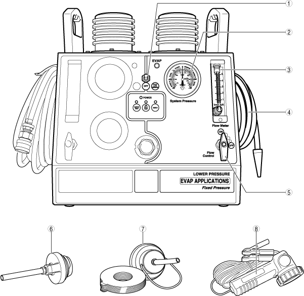
Dual purpose diagnostic leak detector (EVAP/low pressure) component parts
ac3uuw00002556
|
|
1
|
EVAP testing indicator
|
|
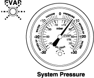
2
|
System pressure
|
|
3
|
Flow meter
|
|
4
|
EVAP/low pressure vapor output hose
|
|
5
|
EVAP/low pressure flow control valve
|
|
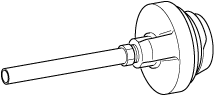
6
|
Gas cap single thread [tool No.: 96-0092]
|
|
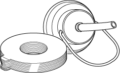
7
|
Universal filler neck connector [tool No.: 95-0011]
|
|
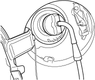
8
|
Halogen inspection light [tool No.: 96-0011]
|
Air only test
1. Move the vehicle to a location where safety can be assured.
2. Ignition switched ON (engine off).
3. Access the following PIDs using the M-MDS. (See PCM INSPECTION [SKYACTIV-G 2.5T].)
4. Remove the fuel-filler cap from the vehicle and clean the fuel-filler cap installation surface of the vehicle.
5. Install the gas cap single thread to the fuel-filler cap installation surface.
acmzzw00000243
|
acmzzw00000244
|
6. Insert the EVAP/low pressure vapor output hose nozzle into the gas cap single thread hose as shown in the figure.
acmzzw00000245
|
7. Toggle the power supply switch to the right to turn on the EVAP/low pressure testing (right side of tester) and verify that the green lamp turns on.
acmzzw00000246
|
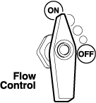
8. Verify that the flow control valves for the EVAP/low pressure testing (right side of tester) and turbo/high pressure testing (left side of tester) are OFF.
acmzzw00000247
|
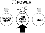
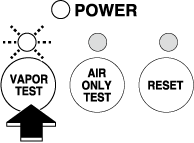
9. Press the [AIR ONLY TEST] button in the center of the tester and verify that the blue lamp turns on.
acmzzw00000248
|
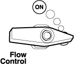
10. Turn the EVAP/low pressure flow control valve for the EVAP/low pressure testing (right side of tester) to ON to send air to the EVAP system.
acmzzw00000249
|
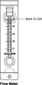
11. Verify that the flow meter for the EVAP/low pressure testing (right side of tester) indicates the maximum flow rate.
acmzzw00000250
|
12. Set the CV solenoid valve (simulation item: EVAPCV) to ON using the M-MDS.
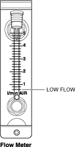
13. Verify that the indication of the flow meter for the EVAP/low pressure testing (right side of tester) decreases to the minimum flow rate.
acmzzw00000251
|
14. Turn the EVAP/low pressure flow control valve for the EVAP/low pressure testing (right side of tester) to OFF.
acmzzw00000247
|
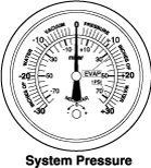
15. Read and record the value indicated by the system pressure gauge for the EVAP/low pressure testing (right side of tester).
acmzzw00000252
|
16. Leave the tester for 2 min.
17. Read the value indicated by the system pressure gauge again and check if there is any change from the value recorded in Step 15.
Vapor test
1. Move the vehicle to a location where safety can be assured.
2. Ignition switched ON (engine off).
3. Access the following PIDs using the M-MDS. (See PCM INSPECTION [SKYACTIV-G 2.5T].)
4. Press the [VAPOR TEST] button in the center of the tester and verify that the red lamp turns on.
acmzzw00000253
|
5. Turn the EVAP/low pressure flow control valve for the EVAP/low pressure testing (right side of tester) to ON.
acmzzw00000249
|
6. Set the value for simulation item EVACP to 50% duty cycle.
7. Remove the evaporative hose inside the engine compartment. (See INTAKE-AIR SYSTEM REMOVAL/INSTALLATION [SKYACTIV-G 2.5T].)
8. Verify that vapor comes out from the evaporative hose.
9. Set the CV solenoid valve (simulation item: EVAPCV) to ON using the M-MDS.
10. Set the value for simulation item EVACP to 0% duty cycle.
11. Leave for 2 min with the EVAP/low pressure flow control valve ON.
12. Monitor the indication of the flow meter for the EVAP/low pressure testing (right side of tester).
13. Verify that vapor is leaking from the evaporative hose.