 |
ac9wzw00005195
REAR CROSSMEMBER REMOVAL/INSTALLATION [4WD]
id0214008010a2
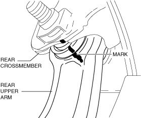
1. Align the rear crossmember component and rear upper arm and mark them.
ac9wzw00005195
|
2. Switch the ignition ON (engine off).
3. Release the electric parking brake.
4. Switch the ignition off.
5. Disconnect the negative battery terminal. (See NEGATIVE BATTERY TERMINAL DISCONNECTION/CONNECTION.)
6. Remove the wheels and tires. (See WHEEL AND TIRE REMOVAL/INSTALLATION.)
7. Drain the differential oil. (See DIFFERENTIAL OIL REPLACEMENT.)
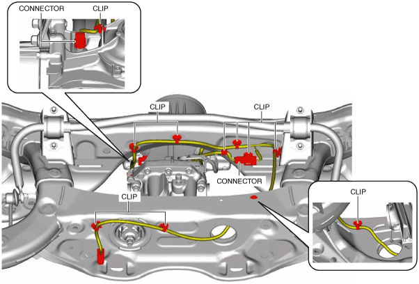
8. Disconnect the wiring harness clips and connectors installed to the rear crossmember.
ac9wzw00005196
|
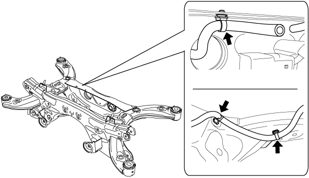
9. Set the rear differential breather hose aside.
am6zzw00012939
|
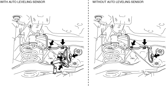
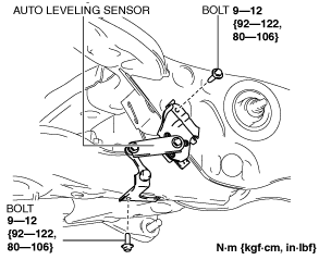
10. Remove the auto leveling sensor. (With auto leveling sensor)
ac4ccw00000692
|
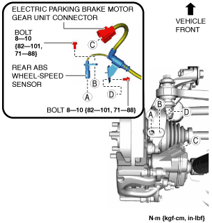
11. Disconnect the rear ABS wheel-speed sensor wiring harness and the electric parking brake motor gear unit connector and set it aside so that it does not interfere with the servicing.
ac4ccw00000649
|
12. Remove the following parts:
ac9uuw00007977
|
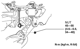
13. Disconnect the rear stabilizer control link from the rear lower arm.
ac9uuw00007978
|
14. Disconnect the rear trailing link from the hub support. (See REAR TRAILING LINK REMOVAL/INSTALLATION.)
15. Remove the rear coil spring. (See REAR COIL SPRING REMOVAL/INSTALLATION.)
16. Disconnect the rear shock absorber from the hub support. (See REAR SHOCK ABSORBER REMOVAL/INSTALLATION.)
17. Disconnect the rear lateral link from the hub support. (See REAR LATERAL LINK REMOVAL/INSTALLATION.)
18. Disconnect the rear upper arm from the hub support. (See REAR UPPER ARM REMOVAL/INSTALLATION [4WD].)
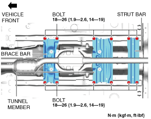
19. Remove the following parts:
20. Remove in the order indicated in the table.
21. Install in the reverse order of removal. (See Suspension Links Installation Note.)
22. Add differential oil. (See DIFFERENTIAL OIL REPLACEMENT.)
23. Inspect the wheel alignment and adjust it if necessary. (See REAR WHEEL ALIGNMENT.)
24. Perform the headlight auto leveling system initial setting. (With auto leveling sensor) (See HEADLIGHT AUTO LEVELING SYSTEM INITIALIZATION.)
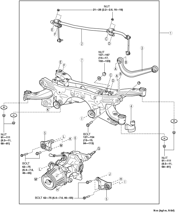
ac9uuw00007979
|
|
1
|
Rear crossmember component
|
|
2
|
Rear stabilizer component
|
|
3
|
Rear upper arm
|
|
4
|
Rear crossmember mudguard
|
|
5
|
Front differential mounting rubber
|
|
6
|
Rear differential
|
|
7
|
Rear crossmember
|
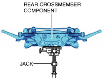
Rear Crossmember Component Removal Note
1. Support the rear crossmember with the jack and remove the nut.
ac9uuw00007980
|
2. Remove the rear crossmember component.
3. Disconnect the wiring harness clips and connector shown in the figure.
ac9uuw00007981
|
Suspension Links Installation Note
1. When installing the joint sections with rubber bushings, perform the following procedures.
Rear Crossmember Component Installation Note
1. Assemble the wiring harness clips and connector shown in the figure.
ac9uuw00007981
|
2. Support the rear crossmember component and install the rear crossmember.
ac9uuw00007980
|