 |
ac9uuw00007599
AIRFLOW MODE MAIN LINK INSTALLATION
id071100811100
L.H.D.
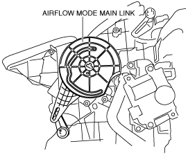
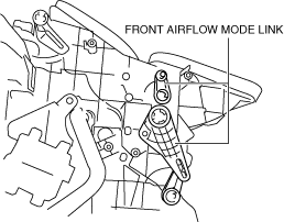
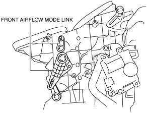
1. Move the front airflow mode links to the positions shown in the figure.
ac9uuw00007599
|
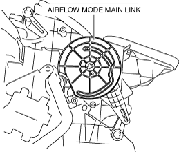
2. Install the airflow mode main link in the direction shown in the figure. (See Airflow mode main link installation note.)
ac9uuw00007600
|
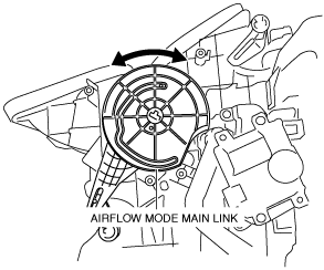
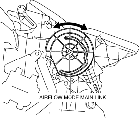
3. Move the airflow mode main link in the direction shown in the figure and verify that it rotates smoothly.
ac9uuw00007601
|
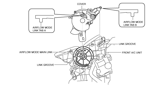
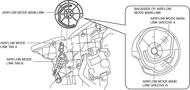
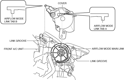
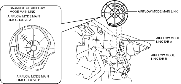
4. Align airflow mode link tab A of the cover with the link groove on the airflow mode main link side, airflow mode link tab B of the cover with the link groove on the front A/C unit side as shown in the figure, and install the cover.
ac9uuw00007602
|
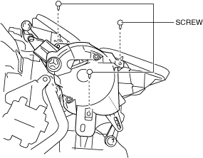
5. Verify that the airflow mode link tabs are engaged with the link grooves.
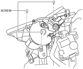
6. Install the screws.
ac9uuw00007603
|
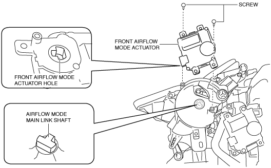
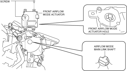
7. Align the airflow mode main link shaft with the shape of the front airflow mode actuator hole, and install the front airflow mode actuator.
ac9uuw00007604
|
8. Install the screws.
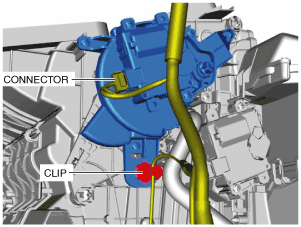
9. Connect the connector.
ac9uuw00007605
|
10. Install the clip.
11. Install the following parts:
12. Connect the negative battery terminal. (See NEGATIVE BATTERY TERMINAL DISCONNECTION/CONNECTION.)
Airflow mode main link installation note
1. When installing the airflow mode main link, verify that airflow mode link tab A is installed in airflow mode main link groove A and airflow mode link tab B is installed in airflow mode main link groove B.
ac9wzw00004335
|
R.H.D.
1. Move the front airflow mode links to the positions shown in the figure.
ac9wzw00003689
|
2. Install the airflow mode main link in the direction shown in the figure. (See Airflow mode main link installation note.)
ac9wzw00003690
|
3. Move the airflow mode main link in the direction shown in the figure and verify that it rotates smoothly.
ac9wzw00003691
|
4. Align airflow mode link tab A of the cover with the link groove on the airflow mode main link side, airflow mode link tab B of the cover with the link groove on the front A/C unit side as shown in the figure, and install the cover.
ac9wzw00003692
|
5. Verify that the airflow mode link tabs are engaged with the link grooves.
6. Install the screws.
ac9wzw00003693
|
7. Align the airflow mode main link shaft with the shape of the front airflow mode actuator hole, and install the front airflow mode actuator.
ac9wzw00003694
|
8. Install the screws.
9. Connect the connector.
ac9wzw00003695
|
10. Install the clip.
11. Install the following parts:
12. Connect the negative battery terminal. (See NEGATIVE BATTERY TERMINAL DISCONNECTION/CONNECTION.)
Airflow mode main link installation note
1. When installing the airflow mode main link, verify that airflow mode link tab A is installed in airflow mode main link groove A and airflow mode link tab B is installed in airflow mode main link groove B.
ac9wzw00004336
|