ac9uuw00007880
|
DTC P0442:00, P0455:00 [PCM (SKYACTIV-G 2.5T)]
id0102s8930000
Details On DTCs
|
DESCRIPTION |
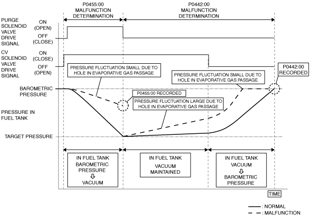
P0442:00 • Evaporative gas leakage (leakage amount: low)
P0455:00 • Evaporative gas leakage (leakage amount: large)
|
|
|---|---|---|
|
DETECTION CONDITION
|
Determination conditions
|
P0442:00
• Hole of 0.04 in (1.0 mm) or more in evaporative gas passage
|
|
P0455:00
• Hole of 0.09 in (2.25 mm) or more in evaporative gas passage
|
||
|
Preconditions
|
• Period ignition is switched off before engine starts: 120 min or more
• Engine coolant temperature at engine start: 2—43 °C {36—109 °F}*1
• Time elapsed from engine start: 6—90 min
• Fuel level in fuel tank: 10—90 %*1
• Desired ambient air temperature: 4.4—43.3 °C {40—109 °F}*1
• Barometric pressure: 72.23 kPa {0.7365 kgf/cm2, 10.48 psi} or more*1
• Charging efficiency: 3—65 %*1
• Vehicle speed: 64—144 km/h {40.0—89.4 mph}*1
*1: Standard can be verified by displaying PIDs using M-MDS
|
|
|
Malfunction determination period
|
• 75 s period
|
|
|
Drive cycle
|
• 2
|
|
|
Self test type
|
• CMDTC self test
|
|
|
Sensor used
|
• Fuel tank pressure sensor
|
|
|
FAIL-SAFE FUNCTION
|
• Not applicable
|
|
|
VEHICLE STATUS WHEN DTCs ARE OUTPUT
|
• Illuminates check engine light.
• Heating is ineffective after engine is started
|
|
|
POSSIBLE CAUSE
|
• Missing or loose fuel filler cap
• Fuel filler cap malfunction
• Fuel tank pressure sensor malfunction
• CV solenoid valve malfunction
• Purge solenoid valve malfunction
• Evaporative gas passage malfunction
• Charcoal canister malfunction
• Catch tank malfunction
• Fuel pump unit loose
• Fuel tank malfunction
• PCM malfunction
|
|
System Wiring Diagram
Function Explanation (DTC Detection Outline)
ac9uuw00007880
|
Repeatability Verification Procedure
PID Item/Simulation Item Used In Diagnosis
PID/DATA monitor item table
|
Item |
Definition |
Unit |
Condition/Specification |
|---|---|---|---|
|
BARO
|
Actually measured barometric pressure input from barometric pressure sensor built into PCM
|
KPa {MPa}, mBar {Bar}, psi, in H20
|
• Displays BARO
|
|
EVAPCP
|
Purge solenoid valve control duty value
|
%
|
• Idle (after warm up): 0% (Engine coolant temperature 59 °C {140 °F} or less)
• Racing (Engine speed 2,000 rpm): 33—35% (ECT is 94 °C {201 °F})
• Racing (Engine speed 4,000 rpm): 53—55% (ECT is 94 °C {201 °F})
|
|
EVAPCV
|
CV solenoid valve operation status
|
Off/On
|
• Simulation item (EVAPCV) is ON: On
|
|
FCL
|
Check fuel cap warning light illumination status
|
Off/On
|
• Check fuel cap warning light not illuminated: Off
• Check fuel cap warning light illuminated: On
|
|
FTP
|
Fuel tank pressure
|
Pa {KPa}, mBar {Bar}, psi, in H20
|
• Displays fuel tank pressure
|
|
Fuel tank pressure sensor voltage
|
V
|
• Fuel tank pressure is equal to barometric pressure: Approx. 2.6 V
|
Function Inspection Using M-MDS
|
STEP |
INSPECTION |
RESULTS |
ACTION |
|---|---|---|---|
|
1
|
PURPOSE: VERIFY RELATED SERVICE INFORMATION AVAILABILITY
• Verify related Service Information availability.
• Is any related Service Information available?
|
Yes
|
Perform repair or diagnosis according to the available Service Information.
• If the vehicle is not repaired, go to the next step.
|
|
No
|
Go to the next step.
|
||
|
2
|
PURPOSE: RECORD FREEZE FRAME DATA/SNAPSHOT DATA AND DIAGNOSTIC MONITORING TEST RESULTS TO UTILIZE WITH REPEATABILITY VERIFICATION
• Record the FREEZE FRAME DATA/snapshot data and DIAGNOSTIC MONITORING TEST RESULTS (EVAP system related) on the repair order.
|
—
|
Go to the next step.
|
|
3
|
PURPOSE: VERIFY IF DIAGNOSTIC RESULT IS AFFECTED BY MALFUNCTION OF CONTROL PART REQUIRED FOR DIAGNOSIS
• Perform the Pending Trouble Code Access Procedure and DTC Reading Procedure.
• Is the PENDING CODE/DTC P0443:00, P0446:00, P0451:00, P0452:00 or P0453:00 also present?
|
Yes
|
Go to the applicable PENDING CODE or DTC inspection.
|
|
No
|
Go to the next step.
|
||
|
4
|
PURPOSE: VERIFY FUEL FILLER CAP MALFUNCTION
• Access the FCL PID using the M-MDS.
• Is the FCL PID value On?
|
Yes
|
Go to the troubleshooting procedure to perform the procedure from Step 1.
|
|
No
|
Go to the next step.
|
||
|
5
|
PURPOSE: SPECIFY LOCATION OF EVAPORATIVE GAS LEAKAGE (FUEL TANK SIDE)
• Disconnect the evaporative hose of the following:
• Plug the charcoal canister.
• Open the fuel-filler cap.
• Access the following PIDs using the M-MDS:
• Does the FTP PID value correspond to the BARO PID value?
|
Yes
|
Go to the next step.
|
|
No
|
Go to the troubleshooting procedure to perform the procedure from Step 3.
|
||
|
6
|
PURPOSE: SPECIFY LOCATION OF EVAPORATIVE GAS LEAKAGE (CHARCOAL CANISTER SIDE)
• Reconnect all the removed parts.
• Disconnect the evaporative hose of the following:
• Plug the evaporative hoses (purge solenoid valve side and CV solenoid valve side).
• Access the following PIDs using the M-MDS:
• Does the FTP PID value correspond to the BARO PID value?
|
Yes
|
Go to the next step.
|
|
No
|
Go to the troubleshooting procedure to perform the procedure from Step 6.
|
||
|
7
|
PURPOSE: DETERMINE IF MALFUNCTION CAUSED BY CONTROL PART (PURGE SOLENOID VALVE) REQUIRED FOR DIAGNOSIS
• Reconnect all the removed parts.
• Start the engine and idle it.
• Access the EVAPCP PID using the M-MDS.
• Is the EVAPCP PID value normal?
|
Yes
|
Go to the next step.
|
|
No
|
Go to the troubleshooting procedure to perform the procedure from Step 9.
|
||
|
8
|
PURPOSE: DETERMINE IF MALFUNCTION CAUSED BY CONTROL PART (CV SOLENOID VALVE) REQUIRED FOR DIAGNOSIS
• Start the engine and idle it.
• Access the EVAPCV PID using the M-MDS.
• Is the EVAPCV PID value normal?
|
Yes
|
Go to the next step.
|
|
No
|
Go to the troubleshooting procedure to perform the procedure from Step 10.
|
||
|
9
|
PURPOSE: DETERMINE IF MALFUNCTION CAUSED BY CONTROL PART (FUEL TANK PRESSURE SENSOR) REQUIRED FOR DIAGNOSIS
• Start the engine and idle it.
• Access the FTP PID using the M-MDS.
• Is the FTP PID value normal?
|
Yes
|
Go to the troubleshooting procedure to perform the procedure from Step 1.
|
|
No
|
Go to the troubleshooting procedure to perform the procedure from Step 11.
|
||
|
10
|
PURPOSE: INSPECTION OF EVAPORATIVE GAS LEAKAGE
• Test the EVAP system for leakage using the dual purpose diagnostic leak detector.
• Is evaporative gas leakage detected?
|
Yes
|
Repair or replace the malfunctioning part.
Go to Troubleshooting Diagnostic Procedure to perform the procedure from Step 12.
|
|
No
|
Go to Troubleshooting Diagnostic Procedure to perform the procedure from Step 1.
|
Troubleshooting Diagnostic Procedure
|
STEP |
INSPECTION |
RESULTS |
ACTION |
|---|---|---|---|
|
1
|
PURPOSE: INSPECTION OF EVAPORATIVE GAS LEAKAGE FROM FUEL-FILLER CAP
• Verify that the fuel-filler cap is completely closed.
• Is the fuel-filler cap completely closed?
|
Yes
|
Go to the next step.
|
|
No
|
Close the fuel-filler cap completely, then go to Step 12.
|
||
|
2
|
PURPOSE: DETERMINE INTEGRITY OF FUEL FILLER CAP
• Inspect the fuel filler cap.
• Is there any malfunction?
|
Yes
|
Replace the fuel filler cap, then go to Step 12.
|
|
No
|
Go to the next step.
|
||
|
3
|
PURPOSE: INSPECTION OF EVAPORATIVE GAS LEAKAGE FROM EVAPORATIVE GAS PASSAGE
• Verify the hoses between the following parts, pipe connection condition, and that there is no cracking or damage.
• Is there any malfunction?
|
Yes
|
Repair or replace the malfunctioning part according to the inspection results, then go to Step 12.
|
|
No
|
Go to the next step.
|
||
|
4
|
PURPOSE: INSPECTION OF EVAPORATIVE GAS LEAKAGE CAUSED BY POOR INSTALLATION OF FUEL PUMP
• Verify the fuel pump unit installation condition (clearance between affixing surfaces, installation angle).
• Is the fuel pump unit installed securely?
|
Yes
|
Go to the next step.
|
|
No
|
Retighten the fuel pump unit, then go to Step 12.
|
||
|
5
|
PURPOSE: DETERMINE INTEGRITY OF FUEL TANK
• Inspect the fuel tank.
• Is there any malfunction?
|
Yes
|
Replace the fuel tank, then go to Step 12.
|
|
No
|
Go to the next step.
|
||
|
6
|
PURPOSE: INSPECTION OF EVAPORATIVE GAS LEAKAGE FROM EVAPORATIVE GAS PASSAGE
• Verify the hoses between the following parts, pipe connection condition, and that there is no cracking or damage.
• Is there any malfunction?
|
Yes
|
Repair or replace the malfunctioning part according to the inspection results, then go to Step 12.
|
|
No
|
Go to the next step.
|
||
|
7
|
PURPOSE: DETERMINE INTEGRITY OF CHARCOAL CANISTER
• Inspect the charcoal canister.
• Is there any malfunction?
|
Yes
|
Replace the charcoal canister, then go to Step 12.
|
|
No
|
Go to the next step.
|
||
|
8
|
PURPOSE: DETERMINE INTEGRITY OF CATCH TANK
• Inspect the catch tank.
• Is there any malfunction?
|
Yes
|
Replace the catch tank, then go to Step 12.
|
|
No
|
Go to the next step.
|
||
|
9
|
PURPOSE: DETERMINE INTEGRITY OF PURGE SOLENOID VALVE
• Inspect the purge solenoid valve.
• Is there any malfunction?
|
Yes
|
Replace the purge solenoid valve, then go to Step 12.
|
|
No
|
Go to the next step.
|
||
|
10
|
PURPOSE: DETERMINE INTEGRITY OF CV SOLENOID VALVE
• Inspect the CV solenoid valve.
• Is there any malfunction?
|
Yes
|
Replace the CV solenoid valve, then go to Step 12.
|
|
No
|
Go to the next step.
|
||
|
11
|
PURPOSE: DETERMINE INTEGRITY OF FUEL TANK PRESSURE SENSOR
• Inspect the fuel tank pressure sensor.
• Is there any malfunction?
|
Yes
|
Replace the charcoal canister, then go to the next step.
|
|
No
|
Go to the next step.
|
||
|
12
|
PURPOSE: VERIFICATION OF VEHICLE REPAIR COMPLETION
• Reconnect all the removed parts.
• Clear the DTC from the PCM memory using the M-MDS.
• Implement the repeatability verification procedure.
• Perform the Pending Trouble Code Access Procedure.
• Is the PENDING CODE for this DTC present?
|
Yes
|
Repeat the inspection from Step 1 of the troubleshooting diagnostic procedure.
• If the malfunction recurs, replace the PCM.
Go to the next step.
|
|
No
|
Go to the next step.
|
||
|
13
|
PURPOSE: VERIFY IF THERE IS ANY OTHER MALFUNCTION
• Is any other DTC or pending code stored?
|
Yes
|
Go to the applicable DTC inspection.
|
|
No
|
DTC troubleshooting completed.
|