 |
ac9wzw00005129
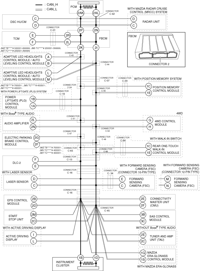
DETERMINING SHORT BETWEEN CIRCUITS LOCATION (HS-CAN) [L.H.D.]
id100225000800
System wiring diagram
ac9wzw00005129
|
Determination Procedure
|
Step |
Inspection |
Action |
|
|---|---|---|---|
|
1
|
INSPECT BETWEEN FRONT BODY CONTROL MODULE (FBCM) AND INSTRUMENT CLUSTER FOR SHORT BETWEEN CIRCUITS
• Disconnect the negative battery terminal.
• Disconnect connector 2 which has front body control module (FBCM) terminals 2K and 2I.
• Connect the negative battery terminal.
• Switch the ignition ON (engine off).
• Measure the voltage at DLC-2 terminals F and E.
• Is the voltage at DLC-2 terminals F and E the same?
|
Yes
|
Go to Step 11.
|
|
No
|
Go to the next step.
|
||
|
2
|
INSPECT FRONT BODY CONTROL MODULE (FBCM) FOR SHORT BETWEEN CIRCUITS
• Switch the ignition off (LOCK).
• Disconnect the negative battery terminal.
• Inspect for continuity between front body control module (FBCM) terminals 2K and 2I.
• Is there continuity?
|
Yes
|
Replace the front body control module (FBCM) because there is a short between circuits in the front body control module (FBCM).
|
|
No
|
Go to the next step.
|
||
|
3
|
INSPECT BETWEEN TCM AND FRONT BODY CONTROL MODULE (FBCM) FOR SHORT BETWEEN CIRCUITS
• Inspect for continuity between TCM terminals E and F.
• Is there continuity?
|
Yes
|
Go to the next step.
|
|
No
|
Go to Step 6.
|
||
|
4
|
INSPECT BETWEEN TCM AND CONNECTOR C-01 FOR SHORT BETWEEN CIRCUITS
• Disconnect connector C-01.
• Inspect for continuity between TCM terminals E and F.
• Is there continuity?
|
Yes
|
Go to the next step.
|
|
No
|
Repair or replace the wiring harness between the front body control module (FBCM) and connector C-01 because the wiring harness is shorted between circuits.
|
||
|
5
|
INSPECT TCM FOR SHORT BETWEEN CIRCUITS
• Disconnect the TCM connector.
• Inspect for continuity between TCM terminals E and F (wiring harness side).
• Is there continuity?
|
Yes
|
Repair or replace the wiring harness between the TCM and connector C-01 because the wiring harness is shorted between circuits.
|
|
No
|
Replace the TCM because there is a short between circuits in the TCM.
|
||
|
6
|
INSPECT BETWEEN FRONT BODY CONTROL MODULE (FBCM) AND CONNECTOR C-42 FOR SHORT BETWEEN CIRCUITS
• Disconnect connector C-42.
• Connect connector 2 which has front body control module (FBCM) terminals 2K and 2I.
• Connect the negative battery terminal.
• Switch the ignition ON (engine off).
• Measure the voltage at DLC-2 terminals F and E.
• Is the voltage at DLC-2 terminals F and E the same?
|
Yes
|
Repair or replace the wiring harness between the front body control module (FBCM) and connector C-42 because the wiring harness is shorted between circuits.
|
|
No
|
Go to the next step.
|
||
|
7
|
INSPECT BETWEEN DSC HU/CM AND CONNECTOR C-42 FOR SHORT BETWEEN CIRCUITS
• Switch the ignition off (LOCK).
• Disconnect the negative battery terminal.
• Inspect for continuity between DSC HU/CM terminals C and D.
• Is there continuity?
|
Yes
|
Go to the next step.
|
|
No
|
Go to Step 9.
|
||
|
8
|
INSPECT DSC HU/CM FOR SHORT BETWEEN CIRCUITS
• Disconnect the DSC HU/CM connector.
• Inspect for continuity between DSC HU/CM terminals C and D (wiring harness side).
• Is there continuity?
|
Yes
|
Repair or replace the wiring harness between the DSC HU/CM and connector C-42 because the wiring harness is shorted between circuits.
|
|
No
|
Replace the DSC HU/CM because there is a short between circuits in the DSC HU/CM.
|
||
|
9
|
INSPECT BETWEEN RADAR UNIT AND CONNECTOR C-42 FOR SHORT BETWEEN CIRCUITS
• Inspect for continuity between radar unit terminals D and C.
• Is there continuity?
|
Yes
|
Go to the next step.
|
|
No
|
Go to Step 51.
|
||
|
10
|
INSPECT RADAR UNIT FOR SHORT BETWEEN CIRCUITS
• Disconnect the radar unit connector.
• Inspect for continuity between radar unit terminals D and C (wiring harness side).
• Is there continuity?
|
Yes
|
Repair or replace the wiring harness between the radar unit and connector C-42 because the wiring harness is shorted between circuits.
|
|
No
|
Replace the radar unit because there is a short between circuits in the radar unit.
|
||
|
11
|
INSPECT BETWEEN CONNECTORS C-43, C-44 AND INSTRUMENT CLUSTER FOR SHORT BETWEEN CIRCUITS
• Switch the ignition off (LOCK).
• Disconnect the negative battery terminal.
• Disconnect connectors C-43, C-44.
• Connect the negative battery terminal.
• Switch the ignition ON (engine off).
• Measure the voltage at DLC-2 terminals F and E.
• Is the voltage at DLC-2 terminals F and E the same?
|
Yes
|
Go to Step 14.
|
|
No
|
Go to the next step.
|
||
|
12
|
INSPECT BETWEEN ADAPTIVE LED HEADLIGHTS CONTROL MODULE / AUTO LEVELING CONTROL MODULE AND CONNECTORS C-43, C-44 FOR SHORT BETWEEN CIRCUITS
• Switch the ignition off (LOCK).
• Disconnect the negative battery terminal.
• Inspect for continuity between adaptive LEDheadlights control module / auto leveling controlmodule terminals A and B. (JMZ TB*****# 500001-699999,JM5 TC*****# 200001-399999,JM7 TC*****# 200001-399999)
• Inspect for continuity between adaptive LEDheadlights control module / auto leveling controlmodule terminals A and B. (JMZ TB*****# 700001-,JM5 TC*****# 400001-, JM7 TC*****# 400001-)
• Is there continuity?
|
Yes
|
Go to the next step.
|
|
No
|
Repair or replace the wiring harness between front body control module (FBCM) and connectors C-43, C-44 because the wiring harness is shorted between circuits.
|
||
|
13
|
INSPECT ADAPTIVE LED HEADLIGHTS CONTROL MODULE / AUTO LEVELING CONTROL MODULE FOR SHORT BETWEEN CIRCUITS
• Disconnect the adaptive LED headlights control module / auto leveling control module connector.
• Inspect for continuity between adaptive LED headlights control module / auto leveling control module terminals A and B (wiring harness side). (JMZ TB*****# 500001-699999,JM5 TC*****# 200001-399999,JM7 TC*****# 200001-399999)
• Inspect for continuity between adaptive LED headlights control module / auto leveling controlmodule terminals L and M (wiring harness side). (JMZ TB*****# 700001-, JM5 TC*****# 400001-, JM7 TC*****# 400001-)
• Is there continuity?
|
Yes
|
Repair or replace the wiring harness between the adaptive LED headlights control module / auto leveling control module and connectors C-43, C-44 because the wiring harness is shorted between circuits.
|
|
No
|
Replace the adaptive LED headlights control module / auto leveling control module because there is a short between circuits in the adaptive LED headlights control module / auto leveling control module.
|
||
|
14
|
INSPECT BETWEEN CONNECTOR C-07 AND INSTRUMENT CLUSTER FOR SHORT BETWEEN CIRCUITS
• Switch the ignition off (LOCK).
• Disconnect the negative battery terminal.
• Disconnect connector C-07.
• Connect the negative battery terminal.
• Switch the ignition ON (engine off).
• Measure the voltage at DLC-2 terminals F and E.
• Is the voltage at DLC-2 terminals F and E the same?
|
Yes
|
Go to the next step.
|
|
No
|
Repair or replace the wiring harness between connector C-07 and connectors C-43, C-44 because the wiring harness is shorted between circuits.
|
||
|
15
|
INSPECT BETWEEN CONNECTORS C-54, C-55 AND INSTRUMENT CLUSTER FOR SHORT BETWEEN CIRCUITS
• Switch the ignition off (LOCK).
• Disconnect the negative battery terminal.
• Disconnect connectors C-54, C-55.
• Connect the negative battery terminal.
• Switch the ignition ON (engine off).
• Measure the voltage at DLC-2 terminals F and E.
• Is the voltage at DLC-2 terminals F and E the same?
|
Yes
|
Go to Step 19.
|
|
No
|
Go to the next step.
|
||
|
16
|
INSPECT BETWEEN CONNECTORS C-54, C-55 AND POSITION MEMORY CONTROL MODULE FOR SHORT BETWEEN CIRCUITS
• Switch the ignition off (LOCK).
• Disconnect the negative battery terminal.
• Inspect for continuity between position memory control module terminals 1C and 1E.
• Is there continuity?
|
Yes
|
Go to the next step.
|
|
No
|
Repair or replace the wiring harness between connector C-07 and connectors C-54, C-55 because the wiring harness is shorted between circuits.
|
||
|
17
|
INSPECT BETWEEN POSITION MEMORY CONTROL MODULE AND CONNECTOR C-29 FOR SHORT BETWEEN CIRCUITS
• Disconnect connector C-29.
• Inspect for continuity between position memory control module terminals 1C and 1E.
• Is there continuity?
|
Yes
|
Go to the next step.
|
|
No
|
Repair or replace the wiring harness between connectors C-54, C-55 and connector C-29 because the wiring harness is shorted between circuits.
|
||
|
18
|
INSPECT POSITION MEMORY CONTROL MODULE FOR SHORT BETWEEN CIRCUITS
• Disconnect the position memory control module connector.
• Inspect for continuity between position memory control module terminals 1C and 1E (wiring harness side).
• Is there continuity?
|
Yes
|
Repair or replace the wiring harness between the position memory control module and connector C-29 because the wiring harness is shorted between circuits.
|
|
No
|
Replace the position memory control module because there is a short between circuits in the position memory control module.
|
||
|
19
|
INSPECT BETWEEN CONNECTORS C-51, C-52 AND INSTRUMENT CLUSTER FOR SHORT BETWEEN CIRCUITS
• Switch the ignition off (LOCK).
• Disconnect the negative battery terminal.
• Disconnect connectors C-51, C-52.
• Connect the negative battery terminal.
• Switch the ignition ON (engine off).
• Measure the voltage at DLC-2 terminals F and E.
• Is the voltage at DLC-2 terminals F and E the same?
|
Yes
|
Go to Step 26.
|
|
No
|
Go to the next step.
|
||
|
20
|
INSPECT BETWEEN AUDIO AMPLIFIER AND CONNECTORS C-51, C-52 FOR SHORT BETWEEN CIRCUITS
• Switch the ignition off (LOCK).
• Disconnect the negative battery terminal.
• Inspect for continuity between audio amplifier terminals 2L and 2N.
• Is there continuity?
|
Yes
|
Go to the next step.
|
|
No
|
Go to Step 22.
|
||
|
21
|
INSPECT AUDIO AMPLIFIER FOR SHORT BETWEEN CIRCUITS
• Disconnect the audio amplifier connector.
• Inspect for continuity between audio amplifier terminals 2L and 2N (wiring harness side).
• Is there continuity?
|
Yes
|
Repair or replace the wiring harness between the audio amplifier and connectors C-51, C-52 because the wiring harness is shorted between circuits.
|
|
No
|
Replace the audio amplifier because there is a short between circuits in the audio amplifier.
|
||
|
22
|
INSPECT BETWEEN 4WD CONTROL MODULE AND CONNECTORS C-51, C-52 FOR SHORT BETWEEN CIRCUITS
• Inspect for continuity between 4WD control module terminals G and H.
• Is there continuity?
|
Yes
|
Go to the next step.
|
|
No
|
Go to Step 24.
|
||
|
23
|
INSPECT 4WD CONTROL MODULE FOR SHORT BETWEEN CIRCUITS
• Disconnect the 4WD control module connector.
• Inspect for continuity between 4WD control module terminals G and H (wiring harness side).
• Is there continuity?
|
Yes
|
Repair or replace the wiring harness between the 4WD control module and connectors C-51, C-52 because the wiring harness is shorted between circuits.
|
|
No
|
Replace the 4WD control module because there is a short between circuits in the 4WD control module.
|
||
|
24
|
INSPECT BETWEEN POWER LIFTGATE (PLG) CONTROL MODULE AND CONNECTOR C-19 FOR SHORT BETWEEN CIRCUITS
• Disconnect connector C-19.
• Inspect for continuity between power liftgate (PLG) control module terminals 1B and 1A.
• Is there continuity?
|
Yes
|
Go to the next step.
|
|
No
|
Repair or replace the wiring harness between connector C-19 and connectors C-54, C-55 and connectors C-51, C-52 because the wiring harness is shorted between circuits.
|
||
|
25
|
INSPECT POWER LIFTGATE (PLG) CONTROL MODULE FOR SHORT BETWEEN CIRCUITS
• Disconnect the power liftgate (PLG) control module connector.
• Inspect for continuity between power liftgate (PLG) control module terminals 1B and 1A (wiring harness side).
• Is there continuity?
|
Yes
|
Repair or replace the wiring harness between the power liftgate (PLG) control module and connector C-19 because the wiring harness is shorted between circuits.
|
|
No
|
Replace the power liftgate (PLG) control module because there is a short between circuits in the power liftgate (PLG) control module.
|
||
|
26
|
INSPECT BETWEEN CONNECTORS C-47, C-48 AND INSTRUMENT CLUSTER FOR SHORT BETWEEN CIRCUITS
• Switch the ignition off (LOCK).
• Disconnect the negative battery terminal.
• Disconnect connectors C-47, C-48.
• Connect the negative battery terminal.
• Switch the ignition ON (engine off).
• Measure the voltage at DLC-2 terminals F and E.
• Is the voltage at DLC-2 terminals F and E the same?
|
Yes
|
Go to Step 29.
|
|
No
|
Go to the next step.
|
||
|
27
|
INSPECT BETWEEN ELECTRIC PARKING BRAKE CONTROL MODULE AND CONNECTORS C-47, C-48 FOR SHORT BETWEEN CIRCUITS
• Switch the ignition off (LOCK).
• Disconnect the negative battery terminal.
• Inspect for continuity between electric parking brake control module terminals 2G and 2F.
• Is there continuity?
|
Yes
|
Go to the next step.
|
|
No
|
Repair or replace the wiring harness between the connectors C-51, C-52 and connectors C-47, C-48 because the wiring harness is shorted between circuits.
|
||
|
28
|
INSPECT ELECTRIC PARKING BRAKE CONTROL MODULE FOR SHORT BETWEEN CIRCUITS
• Disconnect the electric parking brake control module connector.
• Inspect for continuity between electric parking brake control module terminals 2G and 2F (wiring harness side).
• Is there continuity?
|
Yes
|
Repair or replace the wiring harness between the electric parking brake control module and connectors C-47, -48 because the wiring harness is shorted between circuits.
|
|
No
|
Replace the electric parking brake control module because there is a short between circuits in the electric parking brake control module.
|
||
|
29
|
INSPECT BETWEEN CONNECTORS C-65, C-66 AND INSTRUMENT CLUSTER FOR SHORT BETWEEN CIRCUITS
• Switch the ignition off (LOCK).
• Disconnect the negative battery terminal.
• Disconnect connectors C-65, C-66.
• Connect the negative battery terminal.
• Switch the ignition ON (engine off).
• Measure the voltage at DLC-2 terminals F and E.
• Is the voltage at DLC-2 terminals F and E the same?
|
Yes
|
Go to Step 33.
|
|
No
|
Go to the next step.
|
||
|
30
|
INSPECT BETWEEN CONNECTORS C-65, C-66 AND REAR ONE-TOUCH WALK-IN CONTROL MODULE FOR SHORT BETWEEN CIRCUITS
• Switch the ignition off (LOCK).
• Disconnect the negative battery terminal.
• Inspect for continuity between rear one-touch walk-in control module terminals 1C and 1E.
• Is there continuity?
|
Yes
|
Go to the next step.
|
|
No
|
Repair or replace the wiring harness between connectors C-47,C-48 and connectors C-65, C-66 because the wiring harness is shorted between circuits.
|
||
|
31
|
INSPECT BETWEEN REAR ONE-TOUCH WALK-IN CONTROL MODULE AND CONNECTOR C-64 FOR SHORT BETWEEN CIRCUITS
• Disconnect connector C-64.
• Inspect for continuity between rear one-touch walk-in control module terminals 1C and 1E.
• Is there continuity?
|
Yes
|
Go to the next step.
|
|
No
|
Repair or replace the wiring harness between connectors C-65, C-66 and connector C-64 because the wiring harness is shorted between circuits.
|
||
|
32
|
INSPECT REAR ONE-TOUCH WALK-IN CONTROL MODULE FOR SHORT BETWEEN CIRCUITS
• Disconnect the rear one-touch walk-in control module connector.
• Inspect for continuity between rear one-touch walk-in control module terminals 1C and 1E (wiring harness side).
• Is there continuity?
|
Yes
|
Repair or replace the wiring harness between the rear one-touch walk-in control module and connector C-64 because the wiring harness is shorted between circuits.
|
|
No
|
Replace the rear one-touch walk-in control module because there is a short between circuits in the rear one-touch walk-in control module.
|
||
|
33
|
INSPECT BETWEEN CONNECTOR C-13 AND INSTRUMENT CLUSTER FOR SHORT BETWEEN CIRCUITS
• Switch the ignition off (LOCK).
• Disconnect the negative battery terminal.
• Disconnect connector C-13.
• Connect the negative battery terminal.
• Switch the ignition ON (engine off).
• Measure the voltage at DLC-2 terminals F and E.
• Is the voltage at DLC-2 terminals F and E the same?
|
Yes
|
Go to the next step.
|
|
No
|
Repair or replace the wiring harness between the connector C-13 and connectors C-47, C-48 because the wiring harness is shorted between circuits.
|
||
|
34
|
INSPECT BETWEEN CONNECTOR C-13 AND CONNECTOR C-16 AND DLC-2 FOR SHORT BETWEEN CIRCUITS
• Switch the ignition off (LOCK).
• Disconnect the negative battery terminal.
• Disconnect connector C-16.
• Inspect for continuity between DLC-2 terminals F and E.
• Is there continuity?
|
Yes
|
Repair or replace the wiring harness between connector C-13 and connector C-16 and DLC-2 because the wiring harness is shorted between circuits.
|
|
No
|
Go to the next step.
|
||
|
35
|
INSPECT BETWEEN LASER SENSOR / FORWARD SENSING CAMERA (FSC) AND CONNECTOR C-16 FOR SHORT BETWEEN CIRCUITS
• Inspect for continuity between laser sensor terminals D and C (with laser sensor).
• Inspect for continuity between forward sensing camera (FSC) terminals E and C (with forward sensing camera (FSC) (connector 10-pin type)).
• Inspect for continuity between forward sensing camera (FSC) terminals M and N (with forward sensing camera (FSC) (connector 12-pin type)).
• Is there continuity?
|
Yes
|
Go to the next step.
|
|
No
|
Go to Step 39.
|
||
|
36
|
INSPECT LASER SENSOR FOR SHORT BETWEEN CIRCUITS
• Disconnect the laser sensor connector.
• Inspect for continuity between laser sensor terminals D and C (wiring harness side).
• Is there continuity?
|
Yes
|
• Go to the next step. (connector 10-pin type)
• Go to Step 38. (connector 12-pin type)
|
|
No
|
Replace the laser sensor because there is a short between circuits in the laser sensor.
|
||
|
37
|
INSPECT BETWEEN FORWARD SENSING CAMERA (FSC) AND CONNECTOR C-34 FOR SHORT BETWEEN CIRCUITS
• Disconnect connector C-34.
• Inspect for continuity between forward sensing camera (FSC) terminals E and C.
• Is there continuity?
|
Yes
|
Go to the next step.
|
|
No
|
Repair or replace the wiring harness between the connector C-16 and connector C-34 because the wiring harness is shorted between circuits.
|
||
|
38
|
INSPECT FORWARD SENSING CAMERA (FSC) FOR SHORT BETWEEN CIRCUITS
• Disconnect the forward sensing camera (FSC) connector.
• Inspect for continuity between forward sensing camera (FSC) terminals E and C. (wiring harness side) (connector 10-pin type)
• Inspect for continuity between forward sensing camera (FSC) terminals M and N. (wiring harness side) (connector 12-pin type)
• Is there continuity?
|
Yes
|
• Repair or replace the wiring harness between the forward sensing camera (FSC) and connector C-34 because the wiring harness is shorted between circuits. (connector 10-pin type)
• Repair or replace the wiring harness between the forward sensing camera (FSC) and connector C-16 because the wiring harness is shorted between circuits. (connector 12-pin type)
|
|
No
|
Replace the forward sensing camera (FSC) because there is a short between circuits in the forward sensing camera (FSC).
|
||
|
39
|
INSPECT BETWEEN CONNECTOR C-16 AND CONNECTOR C-45 FOR SHORT BETWEEN CIRCUITS
• Disconnect connector C-45.
• Connect connector C-16.
• Connect the negative battery terminal.
• Switch the ignition ON (engine off).
• Measure the voltage at DLC-2 terminals F and E.
• Is the voltage at DLC-2 terminals F and E the same?
|
Yes
|
Repair or replace the wiring harness between the connector C-16 and connector C-45 because the wiring harness is shorted between circuits.
|
|
No
|
Go to the next step.
|
||
|
40
|
INSPECT BETWEEN EPS CONTROL MODULE AND CONNECTOR C-45 FOR SHORT BETWEEN CIRCUITS
• Switch the ignition off (LOCK).
• Disconnect the negative battery terminal.
• Inspect for continuity between EPS control module terminals 2B and 2D.
• Is there continuity?
|
Yes
|
Go to the next step.
|
|
No
|
Go to Step 42.
|
||
|
41
|
INSPECT EPS CONTROL MODULE FOR SHORT BETWEEN CIRCUITS
• Disconnect the EPS control module connector.
• Inspect for continuity EPS control module terminals 2B and 2D (wiring harness side).
• Is there continuity?
|
Yes
|
Repair or replace the wiring harness between the EPS control module and connector C-45 because the wiring harness is shorted between circuits.
|
|
No
|
Replace the EPS control module because there is a short between circuits in the EPS control module.
|
||
|
42
|
INSPECT BETWEEN SAS CONTROL MODULE AND CONNECTOR C-45 FOR SHORT BETWEEN CIRCUITS
• Inspect for continuity between SAS control module terminals 3B and 3C.
• Is there continuity?
|
Yes
|
Go to the next step.
|
|
No
|
Go to Step 44.
|
||
|
43
|
INSPECT SAS CONTROL MODULE FOR SHORT BETWEEN CIRCUITS
• Disconnect the SAS control module connector.
• Inspect for continuity between SAS control module terminals 3B and 3C (wiring harness side).
• Is there continuity?
|
Yes
|
Repair or replace the wiring harness between SAS control module and connector C-45 because the wiring harness is shorted between circuits.
|
|
No
|
Replace the SAS control module because there is a short between circuits in the SAS control module.
|
||
|
44
|
INSPECT BETWEEN START STOP UNIT AND CONNECTOR C-45 FOR SHORT BETWEEN CIRCUITS
• Inspect for continuity between start stop unit terminals 2M and 2O.
• Is there continuity?
|
Yes
|
Go to the next step.
|
|
No
|
Go to Step 46.
|
||
|
45
|
INSPECT START STOP UNIT FOR SHORT BETWEEN CIRCUITS
• Disconnect the start stop unit connector.
• Inspect for continuity between start stop unit terminals 2M and 2O (wiring harness side).
• Is there continuity?
|
Yes
|
Repair or replace the wiring harness between the start stop unit and connector C-45 because the wiring harness is shorted between circuits.
|
|
No
|
Replace the start stop unit because there is a short between circuits in the start stop unit.
|
||
|
46
|
INSPECT BETWEEN CONNECTIVITY MASTER UNIT (CMU) AND CONNECTOR C-45 FOR SHORT BETWEEN CIRCUITS
• Inspect for continuity between connectivity master unit (CMU) terminals 2E and 2F.
• Is there continuity?
|
Yes
|
Go to the next step.
|
|
No
|
Go to Step 48.
|
||
|
47
|
INSPECT CONNECTIVITY MASTER UNIT (CMU) FOR SHORT BETWEEN CIRCUITS
• Disconnect the connectivity master unit (CMU).
• Inspect for continuity between connectivity master unit (CMU) terminals 2E and 2F (wiring harness side).
• Is there continuity?
|
Yes
|
Repair or replace the wiring harness between connectivity master unit (CMU) and connector C-45 because the wiring harness is shorted between circuits.
|
|
No
|
Replace the connectivity master unit (CMU) because there is a short between circuits in the connectivity master unit (CMU).
|
||
|
48
|
INSPECT BETWEEN ACTIVE DRIVING DISPLAY AND CONNECTOR C-45 FOR SHORT BETWEEN CIRCUITS
• Inspect for continuity between active driving display terminals I and L.
• Is there continuity?
|
Yes
|
Go to the next step.
|
|
No
|
Go to Step 50.
|
||
|
49
|
INSPECT ACTIVE DRIVING DISPLAY FOR SHORT BETWEEN CIRCUITS
• Disconnect the active driving display connector.
• Inspect for continuity active driving display terminals I and L (wiring harness side).
• Is there continuity?
|
Yes
|
Repair or replace the wiring harness between the active driving display and connector C-45 because the wiring harness is shorted between circuits.
|
|
No
|
Replace the active driving display because there is a short between circuits in the active driving display.
|
||
|
50
|
INSPECT BETWEEN TUNER AND AMP UNIT (TAU) AND CONNECTOR C-45 FOR SHORT BETWEEN CIRCUITS
• Inspect for continuity between tuner and amp unit (TAU) terminals 2E and 2C.
• Is there continuity?
|
Yes
|
Go to the next step.
|
|
No
|
Go to Step 52.
|
||
|
51
|
INSPECT TUNER AND AMP UNIT (TAU) FOR SHORT BETWEEN CIRCUITS
• Disconnect the tuner and amp unit (TAU) connector.
• Inspect for continuity tuner and amp unit (TAU) terminals 2E and 2C (wiring harness side).
• Is there continuity?
|
Yes
|
Repair or replace the wiring harness between the tuner and amp unit (TAU) and connector C-45 because the wiring harness is shorted between circuits.
|
|
No
|
Replace the tuner and amp unit (TAU) because there is a short between circuits in the tuner and amp unit (TAU).
|
||
|
52
|
INSPECT BETWEEN MAZDA ERA-GLONASS CONTROL MODULE AND CONNECTOR C-45 FOR SHORT BETWEEN CIRCUITS
• Inspect for continuity between MAZDA ERA-GLONASS control module terminals 1Q and 1S.
• Is there continuity?
|
Yes
|
Go to the next step.
|
|
No
|
Go to Step 54.
|
||
|
53
|
INSPECT MAZDA ERA-GLONASS CONTROL MODULE FOR SHORT BETWEEN CIRCUITS
• Disconnect the MAZDA ERA-GLONASS control module connector.
• Inspect for continuity MAZDA ERA-GLONASS control module terminals 1Q and 1S (wiring harness side).
• Is there continuity?
|
Yes
|
Repair or replace the wiring harness between the MAZDA ERA-GLONASS control module and connector C-45 because the wiring harness is shorted between circuits.
|
|
No
|
Replace the MAZDA ERA-GLONASS control module because there is a short between circuits in the MAZDA ERA-GLONASS control module.
|
||
|
54
|
INSPECT INSTRUMENT CLUSTER FOR SHORT BETWEEN CIRCUITS
• Disconnect the instrument cluster connector.
• Inspect for continuity instrument cluster terminals 1B and 1D (wiring harness side).
• Is there continuity?
|
Yes
|
Repair or replace the wiring harness between the instrument cluster and connector C-45 because the wiring harness is shorted between circuits.
|
|
No
|
Replace the instrument cluster because there is a short between circuits in the instrument cluster.
|
||
|
55
|
INSPECT PCM FOR SHORT BETWEEN CIRCUITS
• Disconnect the PCM connector.
• Inspect for continuity between PCM terminals 2AK and 2AL (wiring harness side).
• Is there continuity?
|
Yes
|
Repair or replace the wiring harness between the PCM and connector C-42 because the wiring harness is shorted between circuits.
|
|
No
|
Replace the PCM because there is a short between circuits in the PCM.
|
||